Key Technologies for Pressure Vessel Testing and Flange Connection Design
Flanges are a common method used in assembling pressure vessels. Conducting in-depth research on the various types of flange joints and the key technologies involved in pressure testing is essential to ensure the safe and reliable operation of these vessels. This study examines the design, manufacturing, welding, and non-destructive testing aspects of pressure vessel construction, with the goal of enhancing the overall design, fabrication processes, and product quality of pressure vessel equipment.
Flanges are commonly used pressure-bearing components in pressure vessels. They are securely welded to the shell, cover, or nozzle openings and connected to external components through fastener bolt holes evenly distributed around the flange. This type of connection is well-suited for pressure vessels subjected to pulsating loads. Classifying flange connections in pressure vessels and conducting non-destructive testing are critical steps to ensure proper design, manufacturing quality, and product safety.
Pressure testing is a vital part of the pressure vessel design and manufacturing process. Its purpose is to verify the vessel’s strength and sealing performance, ensuring safe operation under normal working conditions. Among the key aspects of pressure testing, the selection of the test pressure is especially important. The test pressure must be high enough to effectively evaluate the vessel's strength and tightness, yet must not exceed its load-bearing capacity. A carefully chosen test pressure helps ensure the safety and reliability of the vessel throughout the testing process.
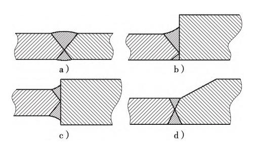
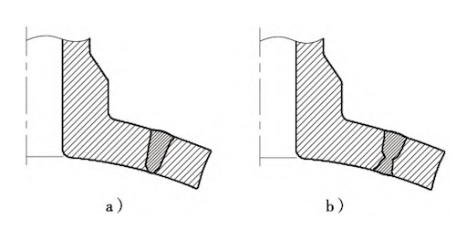
From a welding technology perspective, the common types of welding joints include butt joints, angle joints, T-joints, and lap joints. Among these, butt joint structures are the most commonly used, as shown in Figures 1 and 2.

Figure 1: Butt Joint Structure

Figure 2: Insert Pipe Structure
In pressure vessel engineering, welded connections between pressure-bearing components are classified into four categories: Class A, Class B, Class C, and Class D.
(1) All welds connecting domed or flat heads, as well as those at the junctions of nozzles or flanges with the vessel shell, shall be classified as Class A welds.
(2) Welds connecting pipes (including manway nozzles), flanges, and reinforcing rings to the vessel shell, except those already classified as Class A, B, or C, shall be designated as Class D welds.
According to these classifications, welds involving flanges are categorized as Class A welds due to their structural significance and pressure-retaining function.
Under current pressure vessel standards, flange joints are required to adopt full penetration welding. A full penetration weld is a type of joint in which the weld metal is completely fused with the base material throughout the entire thickness of the joint, achieving strength equivalent to that of the parent material. This means the root and the full depth of the weld must be completely fused without any interruptions. Full penetration welds must ensure complete fusion at the root and throughout the weld zone. These joints are produced through welding processes capable of fully penetrating the groove, ensuring no internal defects such as cracks, lack of fusion, or incomplete penetration. Lack of penetration refers to the incomplete melting of the weld root during welding. Lack of fusion occurs when there is insufficient bonding between the weld metal and the base material, or between successive layers of weld metal. Openings in a pressure vessel compromise its structural integrity, interrupt the continuity of the vessel wall, and create significant stress concentrations, making them the most vulnerable areas. Incomplete penetration reduces joint strength and increases partial stress, thereby lowering the weld's fatigue strength and potentially acting as a source of crack initiation. Due to inadequate bonding, the effective cross-sectional area of the material is reduced, intensifying stress concentrations.
Therefore, from design and manufacturing to welding and non-destructive testing, a complete quality assurance system must be established to ensure the integrity of full penetration weld joints. In addition to surface non-destructive testing, radiographic or ultrasonic testing is also required. In current standards, in addition to specifying acceptance criteria for radiographic and ultrasonic inspection of fillet welds and T-joints, the inspection requirements for Class A and Class B joints are clearly defined. For joints subject to 100% radiographic testing, the acceptance level must be Class II; for spot-checked welds, it must be at least Class D. For ultrasonic testing, the required acceptance level is Class I for full inspection and Class 1 for spot checks. In the case of welded through-hole flange connections in pressure vessels, the requirements are significantly more stringent than those for angle steel or T-joints—only full penetration welds meet Class A standards.
To ensure the safe operation of pressure vessels, pressure testing is an essential procedure. Before performing a pressure test, a thorough inspection of the pressure vessel must be conducted. It is important to confirm that the design, manufacturing, and installation of the vessel comply with relevant standards and specifications. Key aspects to inspect include the material, welds, sealing components, and support structures, to ensure that the vessel can withstand the intended test pressure. In addition, a suitable test medium must be selected. The choice of test medium should consider the vessel’s design parameters and operating environment to ensure compatibility and to avoid issues such as corrosion, leakage, or chemical reactions during testing.
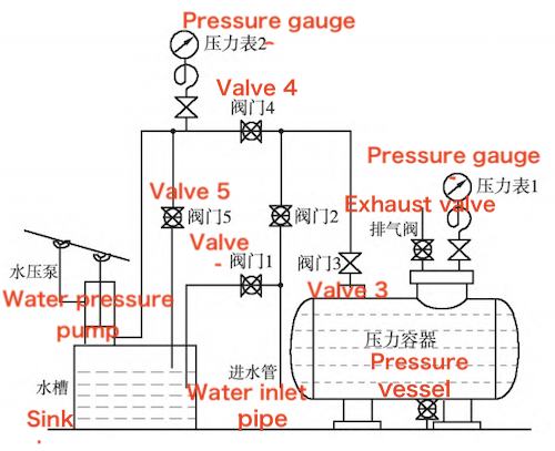
During the test, it is critical to strictly control the test pressure. Based on the vessel’s design pressure and applicable testing standards, the pressure should be increased gradually to ensure a stable testing process. Pressure changes must be continuously monitored to prevent the test pressure from exceeding the vessel’s load capacity. To further ensure safety, management of the test site should be reinforced. The test area must be well-ventilated, and appropriate protective equipment, such as safety goggles, gloves, and ear protection, should be worn. Any potential safety hazards should be promptly identified and addressed to protect both personnel and equipment. After the test, the vessel must undergo a complete post-test inspection. The surface should be examined for cracks, deformation, or other defects. All test records should be properly documented and archived for future analysis and reference (Figure 3).

Figure 3: Hydraulic Test Equipment
Common flange types used in hydraulic testing include raised face (RF) flanges, flat face (FF) flanges, and male-female (MF) flanges. When verifying flange specifications, it is essential to refer to the nominal diameter, pressure rating, flange type, and other relevant information provided in the equipment drawings. Some equipment may use non-standard flanges that are not listed in standard specifications. In such cases, detailed parameters must be obtained by reviewing technical drawings or conducting on-site inspections. Hydraulic tests are typically conducted at room temperature. The materials used by TSD are generally 304 or 316 stainless steel, so a pressure rating of PN20 can be approximately equated to Class 150, which corresponds to 2.0 MPa.
Water replenishment can be categorized into system replenishment, SER source replenishment, and other supplemental methods. When adding water to the SED (or SER) source, it is important to prevent leakage by securing connections with double clamps, using anti-ejection ropes, and fastening joints with blue plastic bags. A designated person should inspect the connection points, and another should monitor the outlet location to prevent accidental overflow or water-related hazards. For other forms of water replenishment, make appropriate preparations to ensure the water quality and to prevent the introduction of foreign substances. During water filling, all gas within the tank must be completely expelled. If needed, the air pressure from the SED (or SER) water supply system can be used to assist with pressurization.
Before conducting the pressure test, it is essential to verify the integrity of the test circuit and ensure that the test equipment is functioning properly. A comprehensive risk assessment must be completed, and all necessary safety measures must be implemented. Surfaces to be inspected should be clean, and the inspection areas must remain clearly visible.
Once the pipe wall temperature reaches the specified value, the pressure increase process can begin. The rate of pressure increase and reduction must comply with the following requirements:
Rate control: The pressure increase rate shall not exceed 1 MPa/min, unless otherwise specified by applicable standards.
Temperature synchronization: Pressure shall be increased only after the material has reached the specified design temperature.
Stepwise pressure increase: Each incremental pressure increase should not exceed 10% of the target test pressure.
Example Parameters:
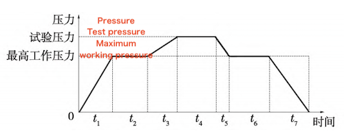
Maximum working pressure of the vessel: 10 MPa (at ambient temperature, [σ]/[σ]t= 1)
Test pressure: 12.5 MPa (1.25 times the maximum working pressure)
Pressure rise curve: Refer to Figure 4, slope = 0.8 MPa/min
Requirements for the Pressure Holding Stage:
Maintain the test pressure for a minimum of 30 minutes.
Allowable pressure fluctuation: ±2% of the test pressure.
Simultaneously record temperature, pressure, and any abnormal observations.

Figure 4: Pressure Rise Curve
Once the pressure reaches the predetermined test value, it must remain stable for at least 10 minutes. During this inspection period, the internal pressure must be consistently maintained. If a slight pressure drop occurs due to minor leakage at the flange surface, intermittent pressure compensation may be applied to preserve stability.
The product is deemed to meet quality standards if the following conditions are satisfied: no water leakage is observed on the inner or outer walls or at the weld seams, and no significant permanent deformation is detected. Minor leakage is acceptable under the following conditions:
① It does not compromise pressure maintenance (with or without intermittent compensation using a water pump).
② It does not interfere with the inspection process.
After pressure holding, the pressure relief valve within the working range should be used to release the pressure back to normal levels. A final inspection must confirm that the vessel shows no significant residual deformation.
Before discharging wastewater, ensure that the air pressure in the water tank has reached the normal operating value. Notify the supervisor in advance, and assign personnel to monitor the drain outlet during the discharge process to prevent leaks caused by excessive drainage speed. If necessary, discharge may be conducted under pressure initially.
System reset involves restoring components to their designated positions and ensuring they are recoverable. This includes disassembling the TSD, restarting operable valves, notifying relevant cooperating units, and cleaning the site after completion. If additional work is planned, the work permit should be returned to the appropriate personnel after the system is reset to ensure timely execution without delaying subsequent tasks.
The following precautions must be observed during the hydraulic testing of pressure vessels:
- Do not tighten bolts under pressure or apply external force to pressure-bearing components.
- Avoid striking pressure test pipes, containers, or accessories.
- When inspecting for leaks on sealing surfaces, personnel must not face the flange directly, and standing opposite the blind plate is strictly prohibited.
- Do not use hammers to check the strength of pipes or containers.
Only by adhering to these safety measures during testing can the quality and performance of the vessel be ensured, guaranteeing its safe operation in practical applications.
Research on flange connection types and key pressure-testing technologies for pressure vessels is essential to ensure their safety and operational effectiveness. This study examines various flange connection methods and pressure-testing techniques, enabling the selection of appropriate connections and proper testing procedures. By implementing these methods, the design and manufacturing quality of pressure vessels can be enhanced, ensuring their safe and reliable performance.
Related News
- Structural Design and Strength Analysis of a Deepwater Riser Suspension Flange
- Analysis of Heat Dissipation Losses in High-Temperature Flanges and Pipelines Used in Oil Refineries
- Failure and Crack Analysis of an EO/EG Unit Tower Inlet Flange
- Pipe Flange Bolt Tightening in LNG Projects: Key Considerations
- Ultrasonic Testing of High-Neck Flange Welds
- Underwater Flange Connection Methods for Submarine Pipelines
- Key Technologies for Pressure Vessel Testing and Flange Connection Design
- Installation of Main Bolts for Lap Joint Flange in High-Temperature Gas-Cooled Reactors
- Structural Design and Finite Element Analysis of Anchor Flanges
- Key Welding Technology for High-Neck Flange and Steel Pipe Joints
