Analyzing Failure of Stainless Steel 304 Flanges in Propylene
Summary
In order to find out the cause of the leakage of stainless steel flanges in the pressure pipes of a polypropylene plant in a petrochemical plant, the cracked and failed stainless steel flanges were detected and analyzed.
The stainless steel flanges in the pressure pipeline of the polypropylene unit of a petrochemical plant leaked at the necks of multiple flanges during operation. After repair welding, the welded parts did not leak in a short time, but other flanges still leaked. The outer wall of the flange is painted, and the medium in the pipe is acrylic. Leakages occurred in the flanges of many pipelines, which directly affected the production of the entire device, causing the entire device to be shut down for maintenance. The cause of the failure of the flange by sampling and analyzing the cracked area and the intact part of the flange. At the same time, suggestions are made to avoid such failures.
1. Working conditions
The stainless steel flange in the pressure pipe of the propylene plant is 0Cr18Ni9. The specification is DN50mm; the operating pressure is 3.6MPa, and the operating temperature is 60°C. The working medium is propylene.
2. The analysis of the sample
2.1 Macro inspection
Macro inspection of the leaked flange shows that there is no obvious corrosion product after the outer wall of the flange has undergone anti-corrosion treatment. The appearance of the PT test is shown in Figure 1. There are two stepped cracks with lengths of 34mm and 12mm along the circumference of the flange neck, and the cracks are near the welding seam on the flange side.
Table 1 The chemical composition of flanges
| Elements | C | Si | Mn | P | S | Ni | Cr |
| Measured values | 0.075 | 0.603 | 0.983 | 0.026 | 0.003 | 18.00 | 8.43 |
| Standard values NB/T 47010-2010 | Less than and equal to 0.080 | Less than and equal to 1.000 | Less than and equal to 2.000 | Less than and equal to 0.035 | Less than and equal to 0.020 | 18.00 to 20.00 | 8.00 to 10.00 |
2.2 The spectral analysis
The flange material was chemically analyzed by a SPECTROLAB direct-reading spectrometer, and the results are shown in Table 1. It can be seen that the chemical composition of the flange meets the requirements of NB/T 47010-2010 for stainless steel.
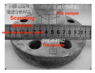
Figure 1 PT detection morphology and sampling
2.3 Metallographic analysis
The crack morphology of the flange is shown in Figure 2. The cracks propagate along the grain from the outside to the inside, and the cracks have penetrated the entire thickness. No cracks from the inside to the outside are found, and the flange raw materials have no obvious non-metallic inclusions. Figure 3a is the microstructure photo of sample 1, the microstructure is austenite, precipitated dispersed carbides, and the material is seriously sensitized; Figure 3b is the microstructure of sample 2; the microstructure is austenite, precipitated dispersed carbides, and there is serious sensitization for the material. Metallographic sample 2 is located far away from the welding seam, and the welding process between the flange and the pipe does not effect the structure of metallographic sample 2.
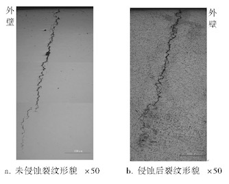
Figure 2 The crack morphology of flanges
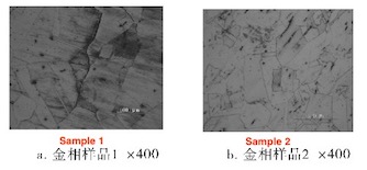
Figure 3 Radial section structure of metallographic samples
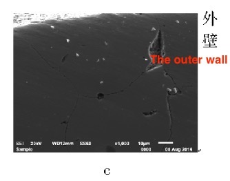
Figure 4 SEM morphology of metallographic sample 1
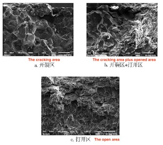
Figure 5 Fracture morphology
2.4 SEM morphology analysis
Scanning electron microscope analysis was performed on the metallographic structure of sample 1, and the results are shown in Figure 4. There are many microcracks on the outer surface of the sample, and the cracks propagate along the grain from the outer wall to the inner wall; in the crack expansion process, the inclusions at the grain boundaries fall off, and it can be inferred that the crack originates from the appearance of multi-source cracks. After the sample was analyzed by a scanning electron microscope. As shown in Figure 5, the cracked area showed a crystalline morphology with secondary cracks, which has a feature of typical intergranular cracking. There are many dimples and torn edges in the opened area.
2.5 EDS analysis
Energy spectrum analysis was carried out on the surface of metallographic sample 1 (Table 2). The energy spectrum analysis was carried out on the opened scanning electron microscope sample (Table 3). The energy spectrum analysis showed that the Cl in the cracked area was 2.14%, and the Cl gradually decreased with the increase in the tear depth; the Cl in the open area is 0%, indicating that Cl- has not exerted stress corrosion effect on the uncracked area of the material.
Table 2 Surface energy spectroscopy analysis results of metallographic sample 1
| Element | Weight/% | Atom/% |
| C K | 6.67 | 14.51 |
| O K | 32.94 | 53.77 |
| Al K | 0.46 | 0.44 |
| Si K | 0.60 | 0.56 |
| S K | 0.76 | 0.62 |
| Cl K | 0.46 | 0.34 |
| Ca K | 12.25 | 7.98 |
| Cr K | 11.55 | 5.80 |
| Fe K | 31.31 | 14.64 |
| Ni K | 3.00 | 1.33 |
Table 3 EDS analysis results of Cl in cracks
| Locations | Weights/% | Atoms/% |
| Crack areas | 2.14 | 2.13 |
| Crack areas and open areas | 0.39 | 0.48 |
| Crack areas and open areas | 0.00 | 0.00 |
Related News
- Failure Analysis of Cracking in a 16MnⅢ Weld Neck Flange
- ANSYS Analysis for Anchor Flange Structural Optimization
- Flange Leakage in Hydrogen-Cooled Pipeline Systems of Thermal Power Plants
- Flange Sealing Technology and Installation Method for Hydrogenation Units
- Multi-Directional Die Forging Process for Horizontal Valve Bodies with Dual Flanges
- Structural Performance Analysis of Zirconium Pressure Vessel Lap Joint Flanges
- Low-Temperature Flange Sealing Solutions for Cryogenic Chemical Pipelines
- Innovative Technology for Automatic Alignment in Underwater Flange Assembly
- Stamped Steel Slip-On Flanges
- Design and Finite Element Analysis of Anchor Flanges for Oil & Gas Pipelines
