Control Deformation Caused by Welding of Slip-on Flanges with Large Diameters
Abstract: In the manufacturing process of pressure vessels, deformation caused by the welding of slip-on flanges with large diameters often occurs. By analyzing the causes of deformation, the measures to control the deformation are proposed to provide guidance for preventing deformation caused by welding of similar workpieces.
After the slip-on flange above DN20 on pressure vessels and pipelines is welded to the cylinder body, the flange end face and flange diameter usually deform. The larger the flange diameter is, the more serious the deformation becomes. The repair after the deformation not being controlled before welding be time-consuming and laborious, which not only causes a waste of material resources, but also is very difficult to repair.
Take the deformation caused by welding of the slip-on flange and the cylinder body of a low-pressure vertical reaction vessel produced by a company as an example to analyze and control the deformation caused by welding of the large-diameter slip-on flange. The general picture of the vessel is shown in Figure 1. The characteristic parameters of the equipment are shown in Table 1. The structure of the flange and vessel is shown in Figure 2.
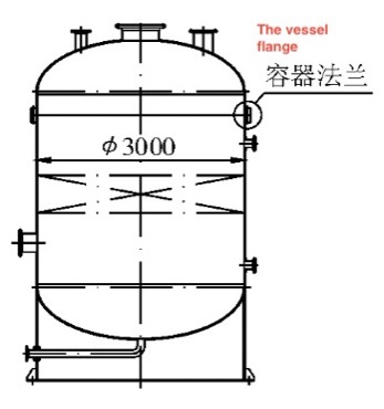
Figure 1 The general picture of the vessel
The assembly and welding process of the flange and the cylinder is as follows: (1) The machined flange is a finished product. (2) The riveter aligns the connection joint between the flange and the cylinder. (3) Manually weld the welding seam between the flange and the cylinder. (4) Inspect the dimension after group welding, and conduct an air tightness inspection of leak detection holes. (5) Weld stainless steel lining rings of flanges. (6) Machine the sealing surface of the lining ring. The specification of welding of the flange and cylinder is shown in Table 2.
Table 1 Container characteristics
After the slip-on flange above DN20 on pressure vessels and pipelines is welded to the cylinder body, the flange end face and flange diameter usually deform. The larger the flange diameter is, the more serious the deformation becomes. The repair after the deformation not being controlled before welding be time-consuming and laborious, which not only causes a waste of material resources, but also is very difficult to repair.
Take the deformation caused by welding of the slip-on flange and the cylinder body of a low-pressure vertical reaction vessel produced by a company as an example to analyze and control the deformation caused by welding of the large-diameter slip-on flange. The general picture of the vessel is shown in Figure 1. The characteristic parameters of the equipment are shown in Table 1. The structure of the flange and vessel is shown in Figure 2.
Figure 1 The general picture of the vessel
The assembly and welding process of the flange and the cylinder is as follows: (1) The machined flange is a finished product. (2) The riveter aligns the connection joint between the flange and the cylinder. (3) Manually weld the welding seam between the flange and the cylinder. (4) Inspect the dimension after group welding, and conduct an air tightness inspection of leak detection holes. (5) Weld stainless steel lining rings of flanges. (6) Machine the sealing surface of the lining ring. The specification of welding of the flange and cylinder is shown in Table 2.
Table 1 Container characteristics
| Items | Parameters | Items | |
| Design pressure/MPa | 0.25 | Materials of cylinders | Q345R |
| Design temperature/°C | 100 | Materials of Vessel flanges | 16MnI I |
| Nominal diameters /mm | 3000 | Materials of lining rings | 06Cr19Ni10 |
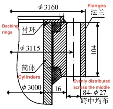
Figure 2 The lower structure of the flange of the vessel
Table 2 Welding specifications for flanges and cylinders
| Welding methods | Grades of Welding electrodes | Sizes of welding materials/mm | The type and polarity of current | Welding current/A |
Welding voltage/V | Welding speeds/ (cm·min-1) |
| SMAW | A302 | 4.0 | DC+ | 120 to 160 | 24 to 26 | 15 to 20 |
After the flange and the cylinder are welded, the relative dimensions of the flange are measured, and the flange of the container is seriously deformed due to welding. The flange surface is turned outward. The picture of the deformation is shown in Figure 3. The measured data can be seen in Table 3.
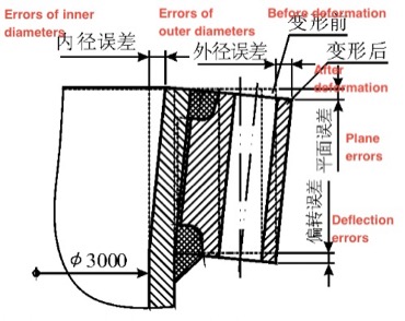
Figure 3 The deformation of the flange after welding
Table 3 Measured data of flanges after flipping
| Angles | The inner diameter of the cylinder on the upper surface of the flange /mm | The outer diameter of the flange/mm |
The diameter error of the center circle of the flange stud hole/mm | Flatness error of the upper surface of the flange/mm |
| 0° | 3009 | 3168 | +9 | -2 |
| 30° | 3005 | 3165 | +5 | -1.5 |
| 60° | 2097 | 3154 | -4 | +1 |
| 90° | 2993 | 3152 | -7 | +2.5 |
| 120° | 2998 | 3157 | -2 | +1.2 |
| 150° | 3010 | 3168 | +10 | -2.5 |
| Standard theoretical values | 3000 | 3160 | ±2 | ±0.3 |
Table 3 shows that there is a very great difference between the measured data and the theoretical value.
1. The analysis of the reasons
When large-diameter slip-on carbon steel flanges are welded to stainless steel cylinders, it takes too long to complete a circle of welding at the welding fusion point due to the large diameter of the flanges, poor rigidity, and long weld bead. In the welding process, the heating and cooling rate of the fusion zone and the intermittent cooling time of the welding seam are too long, resulting in unbalanced heating of the entire circumferential seam. The welding seam shrinks and deforms unevenly.
When the welding adopts single-sided continuous welding, the circumferentially heated part of the flange welding area is subjected to the effect of circumferential shrinkage stress when the welding seam is cooled, and plane deformation occurs. At the same time, because the welding shrinkage in the circumferential direction of the welding seam is very great, the expansion of the deformation is further aggravated, and an irregular ellipse is formed for the flange in the circumferential direction. The partial concave part is convex. At the same time, the perimeter of the inner side of the flange becomes smaller and the outer side of the flange is at a lower temperature due to the welding shrinkage force, so the influence of welding heat input is small; the rigidity is better, and there is no shrinkage. The flange section is twisted significantly. At the same time, the central axis of the flange bolt hole is no longer parallel to the axis of the cylinder. Facts have proved that the force of this flipping is very great, and the deformation cannot be improved after the welding of the groove on the upper end face of the flange and the cylinder is completed.
2. Correct measures
In view of the flange’s deformation caused by welding due to insufficient rigidity and uneven welding heat of the flange, corresponding anti-deformation measures and control of welding line energy input are taken. The inner diameter of the flange is supported, and preheating is performed before welding. The preheating temperature is 50°C, using a welding rod of 3.2mm, low current, continuous welding and controlling the interlayer temperature of the welding bead. The heat input should be uniform, and the overall preheating of the flange should maintain a uniform temperature. When the thickness of the welding metal reaches 5mm, the welding should be stopped and then the workpiece should be turned over so that the back of the flange faces upwards; the groove on the back of the flange is flat-welded. The same low current is used for continuous welding; the interlayer temperature of the weld bead is controlled, and the heat is uniformly input and kept warm. When the welding thickness reaches 5 mm, stop welding; turn the flange over again, and after welding 5 mm, turn the flange over for welding until the welding is completed.
The upper flange of the container is welded in this way, and the actual measurement after welding is as follows: the flatness error of the end face of the flange is 2mm. The ellipse error of the inner diameter of the flange is 3mm. By simply supporting the inner diameter of the flange, the roundness error of the inner diameter of the flange can reach 1.5mm.
3. Conclusion
Large-diameter slip-on flanges and similar large-diameter annular workpieces are easy to deform due to the poor rigidity of the structure, when the rigidity is not reinforced and subjected to uneven partial heat input. The amount of deformation varies according to the heat input. For such workpieces whose thickness is much smaller than their diameters. There should be much rigidity before welding or heating. At the same time, the amount of heat input, the uniformity of heat input and the slow cooling after heating should be controlled during welding and heating.

Related News
- Analysis of Loading-Port Flange Leakage in a Reactor Coolant Purification Resin Bed of a Power Plant
- Structural Design and Strength Analysis of a Deepwater Riser Suspension Flange
- Analysis of Heat Dissipation Losses in High-Temperature Flanges and Pipelines Used in Oil Refineries
- Failure and Crack Analysis of an EO/EG Unit Tower Inlet Flange
- Pipe Flange Bolt Tightening in LNG Projects: Key Considerations
- Ultrasonic Testing of High-Neck Flange Welds
- Underwater Flange Connection Methods for Submarine Pipelines
- Key Technologies for Pressure Vessel Testing and Flange Connection Design
- Installation of Main Bolts for Lap Joint Flange in High-Temperature Gas-Cooled Reactors
- Structural Design and Finite Element Analysis of Anchor Flanges