
High-Precision Machining of Large-Diameter Flange Holes
Abstract: This study aims to improve the machining quality and stability of large-diameter, high-precision holes in flange components, addressing challenges in maintaining dimensional accuracy and preventing post-machining deformation that can reduce the product acceptance rate. The following measures were implemented:
- Thermal stabilization: A thermal stabilization process was introduced after rough machining to control residual stress release and minimize the effects of ambient temperature fluctuations, thereby reducing subsequent deformation.
- Optimization of cutting parameters: Cutting speed and feed rate were systematically adjusted during semi-finish and finish boring. Multiple rounds of testing were conducted to identify optimal parameter combinations for improved dimensional accuracy and surface quality.
- Tool-setting calibration: A dedicated tool-setting test piece was developed to periodically calibrate the machine tool and cutting tools, reducing machining errors and improving process stability.
- Results: Experimental results showed that the machined holes met the specified dimensional tolerances and remained within the allowable range after 48 hours of aging.
- Conclusion: The proposed process optimization measures effectively reduced hole deformation and improved the dimensional accuracy and stability of large-diameter, high-precision flange holes.
As modern industry advances toward greater precision and efficiency, the equipment manufacturing sector faces increasingly stringent requirements for the machining accuracy of critical components. The flange is a key component of the trumpet-mouth transmission mechanism in the ZL29 filter rod forming machine. The machining quality of its large-diameter bore directly affects the sealing performance, connection strength, and operational stability of the entire system.
However, machining large-diameter, high-precision holes remains a significant challenge in mechanical manufacturing. Compared with small- and medium-diameter bores, large-diameter holes present several distinct challenges. First, the long tool overhang and limited tool rigidity make the cutting tool more susceptible to deflection under cutting forces, leading to dimensional instability. Second, cutting heat is difficult to dissipate rapidly, increasing the risk of workpiece thermal deformation and compromising hole geometry. Third, conventional boring and turning processes for large-diameter holes often suffer from low machining efficiency, rapid tool wear, and inadequate surface quality control. Furthermore, the poor machinability of certain specialty materials used in flange manufacturing, including superalloys and stainless steels, makes achieving high machining accuracy even more difficult. Therefore, systematic research into the machining processes for large-diameter, high-precision flange holes, together with the development of efficient, stable, and cost-effective machining methods, is of considerable theoretical significance and practical engineering value. Such research can help improve the manufacturing standards of major equipment in China and ensure the safe operation of critical machinery. This study aims to improve machining quality and process stability through systematic process optimization and to validate the proposed measures experimentally, thereby providing theoretical guidance and technical support for related manufacturing applications.
Flange components have complex geometries and stringent dimensional tolerances across multiple features. The 3D model of the flange is shown in Figure 1. In particular, the drawing specifies a bearing bore diameter of Φ(100 ± 0.011) mm, while the process requirement is Φ100 (+0.005/−0.001) mm, with the target set near the upper tolerance limit. These tight tolerances pose significant challenges for production machining. As a result, multiple batches of parts have been scrapped or accepted under concession because the Φ100 mm bore dimensions failed to meet the specified tolerances.
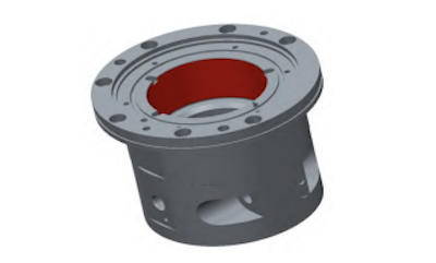
Figure 1. 3D model of the flange
The Φ100 mm bearing bore in the flange is machined through semi-finish boring and finish boring, with a dimensional tolerance grade of js6. The specific dimensions are shown in Figure 2. The main machining challenges are as follows:
- Workpiece deformation caused by residual stress release: Significant material removal and heavy cutting loads can cause internal residual stresses to be released, leading to workpiece deformation. As a result, the bore may lose roundness after the machined part has been left to stand for some time.
- Optimization of machining parameters: The machining allowance before and after semi-finish boring, the spindle speed during finish boring, and the feed rate all affect the final bore dimensions. An optimal combination of process parameters must therefore be determined to ensure dimensional accuracy and consistency.
- Difficulty in setting the boring tool offset: Initial adjustment of the boring tool offset is the most time-consuming step. Although the offset is adjusted during rough boring and the same offset data are used for finish boring, there is still a risk of scrapping the workpiece if insufficient machining allowance remains for the finishing operation, resulting in significant production losses.
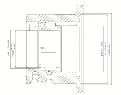
Figure 2. Φ100 mm dimension of the flange component (unit: mm)
To address the machining challenges associated with the Φ100 mm bearing bore in the flange component, this study proposes targeted process improvements, as detailed below.
The flange component is made of 14Cr17Ni2 martensitic stainless steel. To minimize the effects of residual stresses on bore dimensional accuracy, a thermal stabilization process was introduced after rough turning. This process is intended to relieve machining-induced residual stresses, reduce dimensional changes during subsequent machining and service, and minimize the risk of deformation and cracking. It also helps maintain dimensional stability during long-term storage and use, ensuring consistent component geometry and performance.
In this study, one batch of flange components underwent an intermediate thermal stabilization treatment after rough turning, while another batch was processed using the standard procedure for comparison, as shown in Figure 3.
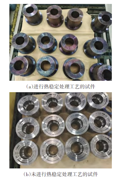
(a) Test specimen after thermal stabilization (b) Test specimen without thermal stabilization
Figure 3. Comparison of flange test specimens
The Φ100 mm bearing bore dimensions of both flange batches were measured after finish machining and again after a 24-hour hold at various temperatures. The results are presented in Table 1.
Table 1. Comparison of Experimental Data
Part ID | Thermal Stabilization | Bore Diameter After Finish Machining (mm) (Ambient Temperature: 26°C) | Bore Diameter After 48 h (mm) (Ambient Temperature: 24°C) | Dimensional Change (mm) |
1 | No | 99.997 | 99.993 | 0.004 |
2 | No | 99.997 | 99.998 | 0.001 |
3 | No | 100.005 | 100.001 | 0.004 |
4 | No | 99.995 | 99.997 | 0.002 |
5 | No | 100.002 | 99.997 | 0.005 |
6 | No | 99.999 | 99.999 | 0.000 |
7 | Yes | 99.998 | 100.000 | 0.002 |
8 | Yes | 99.997 | 99.997 | 0.000 |
9 | Yes | 100.000 | 100.001 | 0.001 |
10 | Yes | 100.005 | 100.004 | 0.001 |
11 | Yes | 99.999 | 100.001 | 0.002 |
12 | Yes | 99.998 | 99.998 | 0.000 |
A comparison of the measurement data for the two flange batches shows that the Φ100 mm bore in the untreated batch exhibited a maximum dimensional change of 0.005 mm after a 48-hour hold, whereas the maximum change in the thermally stabilized batch was only 0.002 mm. These results indicate that thermal stabilization helps reduce dimensional fluctuations in flange components associated with temperature variations.
To identify the optimal machining parameters efficiently while minimizing the number of experimental trials, an orthogonal test method was used to evaluate the effects of different parameters. The spindle speed and feed rate were controlled during both semi-finish boring and finish boring. The factor levels selected for the machining parameters are listed in Table 2.
Table 2. Factor Levels for the Machining Parameters
Factor Level | A: Hole Allowance Before Semi-Finish Boring (mm) | B: Hole Allowance After Semi-Finish Boring (mm) | C: Finish Boring Spindle Speed (r/min) | D: Finish Boring Feed Rate (mm/min) |
1 | 0.2 | 0.1 | 1,200 | 350 |
2 | 0.3 | 0.12 | 1,000 | 300 |
3 | 0.4 | 0.15 | 800 | 250 |
Additionally, the measurement results for each group of flange components were classified into four grades, as shown in Table 3.
Table 3. Machining Quality Grades
Bore Diameter (mm) | Quality Score |
99.999–100.005 | 4 |
100.006–100.009 | 3 |
100.010–100.013 or 99.996–99.998 | 2 |
Other values | 1 |
An L9(3⁴) orthogonal array was used to design the experiments. After machining multiple test specimens, the machining parameters and corresponding quality scores were recorded in the orthogonal array, as detailed in Table 4, and the results were analyzed. Range analysis showed that the hole allowance after semi-finish boring and the spindle speed during finish boring had the largest ranges, indicating that these were the two most influential factors affecting the final Φ100 mm bore diameter. Level 1 was optimal for the hole allowance after semi-finish boring, while Level 3 was optimal for the finish boring spindle speed. Based on the calculations, the optimal parameter combination was determined to be A1B1C3D2, corresponding to a hole allowance of 0.2 mm before semi-finish boring, a hole allowance of 0.1 mm after semi-finish boring, a finish boring spindle speed of 800 r/min, and a finish boring feed rate of 300 mm/min.
During flange machining, initially setting the boring tool offset for the Φ100 mm bore is time-consuming and involves a significant risk of scrapping the workpiece. The conventional approach is to adjust the tool offset during rough boring and use the same offset setting for finish boring. However, if insufficient machining allowance remains for the finishing operation, the workpiece may be scrapped, resulting in substantial economic losses. To mitigate this risk, a dedicated tool-setting test piece was developed. Before machining each batch of production parts, the tool offset is adjusted and verified using the test piece. The tool-setting arrangement is illustrated in Figure 4, and the measurement results for one batch processed using this method are presented in Table 5. This approach ensures that any problems with the machining allowance are identified before production machining begins. Even if an allowance-related issue results in scrapping the test piece, the loss is limited to a low-value test piece rather than a high-value production component, thereby reducing production costs.
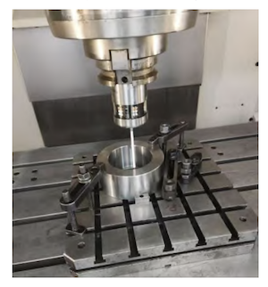
Figure 4. Schematic of tool setting using the test piece
An analysis of the differences between the initial and subsequent tool settings shows that, with the optimized machining parameters, the maximum deviation during initial tool setting using the test piece is 0.002 mm. Given the specified process tolerance of ±0.006 mm, this deviation is well within the allowable range, indicating that the required dimensional accuracy can be readily achieved.
Table 4. L9(3⁴) Orthogonal Array
Test No. | A: Bore Allowance Before Semi-Finish Boring (mm) | B: Bore Allowance After Semi-Finish Boring (mm) | C: Finish Boring Spindle Speed (r/min) | D: Finish Boring Feed Rate (mm/min) | Measured Bore Diameter (mm) | Quality Score |
1 | 1 | 1 | 3 | 2 | 100.003 | 4 |
2 | 2 | 1 | 1 | 1 | 99.998 | 2 |
3 | 3 | 1 | 2 | 3 | 100.010 | 2 |
4 | 1 | 2 | 2 | 1 | 99.995 | 1 |
5 | 2 | 2 | 3 | 3 | 100.007 | 3 |
6 | 3 | 2 | 1 | 2 | 100.015 | 1 |
7 | 1 | 3 | 1 | 3 | 99.995 | 1 |
8 | 2 | 3 | 2 | 2 | 100.011 | 2 |
9 | 3 | 3 | 3 | 1 | 100.014 | 1 |
Table 5. Measurement Results for a Batch of Parts Using the Tool-Setting Test Piece (Unit: mm)
Part No. | Hole Diameter After Initial Tool Setting | Hole Diameter After Subsequent Machining | Difference |
1 | 100.004 | 100.004 | 0.000 |
2 | 100.002 | 100.003 | 0.001 |
3 | 100.000 | 99.999 | 0.001 |
4 | 100.005 | 100.005 | 0.000 |
5 | 100.003 | 100.005 | 0.002 |
6 | 100.004 | 100.004 | 0.000 |
Terminology notes:
Part No. is more natural than “Part ID” in a technical measurement table.
Hole Diameter is more precise than “Size of hole.”
After Initial Tool Setting and After Subsequent Machining clearly distinguish the two measurements.
Difference is sufficient for the final column if the table heading or accompanying text explains which measurements are being compared.
Note that for Part 3, the signed difference is −0.001 mm if calculated as the subsequent measurement minus the initial measurement. The table lists 0.001 mm, indicating that the difference is expressed as an absolute value.
After the improved machining process was implemented, inspection confirmed that all part dimensions and tolerances met the drawing requirements, as shown in Figure 5. In particular, all measured diameters of the Φ100 mm bore were within the specified tolerance range of 100.000 to 100.005 mm.
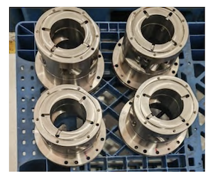
Figure 5. Machining Results for the Flange Component
To address the challenges of machining large-diameter, high-precision flange holes, this study developed a systematic process optimization strategy to improve machining accuracy and stability. The key measures included:
- introducing a thermal stabilization treatment after rough machining to reduce the effects of residual stress and temperature variations on subsequent machining operations.
- optimizing the cutting parameters for semi-finish and finish boring through repeated tests to determine suitable combinations of cutting speed, feed rate, and other critical parameters, thereby improving dimensional accuracy and surface quality
- using dedicated tool-setting test pieces to periodically calibrate the machine tool and cutting tools, reducing errors associated with the equipment and tool-setting process. Experimental results showed that the optimized process consistently kept the dimensional deviations of the large-diameter, high-precision flange holes within the specified tolerance range. The holes also maintained dimensional stability after a 48-hour holding period, demonstrating the effectiveness of the proposed approach in controlling dimensional changes.

Related News
- High-Precision Machining of Large-Diameter Flange Holes
- Failure Analysis of Cracking in a 16MnⅢ Weld Neck Flange
- ANSYS Analysis for Anchor Flange Structural Optimization
- Flange Leakage in Hydrogen-Cooled Pipeline Systems of Thermal Power Plants
- Flange Sealing Technology and Installation Method for Hydrogenation Units
- Multi-Directional Die Forging Process for Horizontal Valve Bodies with Dual Flanges
- Structural Performance Analysis of Zirconium Pressure Vessel Lap Joint Flanges
- Low-Temperature Flange Sealing Solutions for Cryogenic Chemical Pipelines
- Innovative Technology for Automatic Alignment in Underwater Flange Assembly
- Stamped Steel Slip-On Flanges