Measures to Prevent and Control Deformation Caused by Welding
3.1 Welding sequences
In view of the above structural characteristics of welding flanges and cylinders, when compiling the welding process, we can skillfully use the welding stress of the material to make it as far as possible to offset each other in the direction of action, as shown in Figure 3. The inner welding seam A of the flange and cylinder body is welded, and the outer welding seam B is welded. When the welding seam is at the center of the flange plate, the lateral shrinkage of the welding seam has little effect on the angular deformation of the flange. The welding seam A can effectively form a rigid member for the flange and the cylinder, which is beneficial to resist the welding stress and can effectively reduce the deformation of the welding corner. In addition, symmetrical welding is adopted, which is beneficial to controlling the welding seam’s interlayer temperature to be below 60°C.
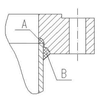
Figure 3
3.2 Rigid fixation
After the welding seam is performed for the flange and cylinder, place it horizontally and fix it on the workbench. Generally, spot welding peripheral rings (as shown in Figure 4) or by the peripheral ring of the pressure plate (as shown in Figure 5). After the welding is completed, the tooling is removed; although slight rebound deformation occurs for the flange, the sealing surface is processed after welding, which can meet the requirements of dimensional accuracy in the standard.
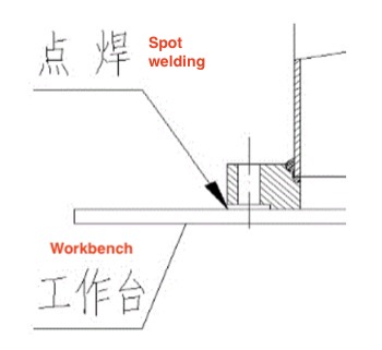
Figure 4
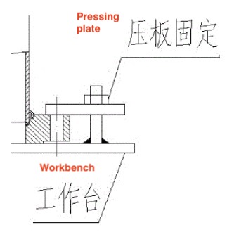
Figure 5
3.3 Pairing of the workpiece
The flanges of the pressure vessel are usually paired or equipped with blind flanges. The two flanges can be pre-paired, and the two sealing surfaces are separated by a tooling gasket. The flanges are spot welded. Spot welding the circle (as shown in Figure 6) or pressing device is adopted (as shown in Figure 7). This can make the two flanges into a whole, increase the rigidity of the flange, and play a very effective role in reducing the deformation of the welding angle. We use the opposite direction of the welding angle deformation of the two flanges, which can offset or reduce part of the welding angle deformation.
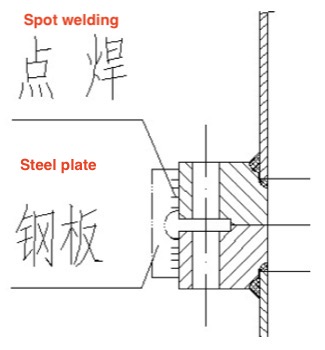
Figure 6
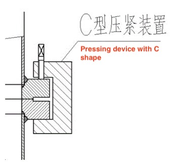
Figure 7
3.4 Internal and external reinforcement
The flange and the cylinder can be reinforced with ribs on the outside if limited by other factors such as site or tooling. The support pipe can be used on the inside to increase the rigidity of the cylinder and flange at the same time, as shown in Figure 8.
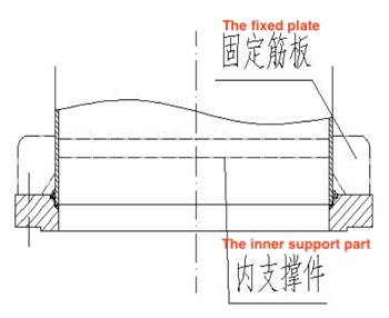
Figure 8
4. Conclusion
According to the above analysis of the causes of deformation caused by welding and the introduction to preventive measures, the reasons for such problems and control methods for the deformation are briefly explained. The workload of post-correction of equipment parts and components, thereby improving production efficiency. It is hoped that attention will be paid to the manufacturing process, and improvements will be made from on-site management to riveting and welding processes to reduce the workload of post-correction of equipment components and improve production efficiency based on the actual situation.

Related News
- Failure Analysis of Cracking in a 16MnⅢ Weld Neck Flange
- ANSYS Analysis for Anchor Flange Structural Optimization
- Flange Leakage in Hydrogen-Cooled Pipeline Systems of Thermal Power Plants
- Flange Sealing Technology and Installation Method for Hydrogenation Units
- Multi-Directional Die Forging Process for Horizontal Valve Bodies with Dual Flanges
- Structural Performance Analysis of Zirconium Pressure Vessel Lap Joint Flanges
- Low-Temperature Flange Sealing Solutions for Cryogenic Chemical Pipelines
- Innovative Technology for Automatic Alignment in Underwater Flange Assembly
- Stamped Steel Slip-On Flanges
- Design and Finite Element Analysis of Anchor Flanges for Oil & Gas Pipelines