Deformation of Stainless Steel Slip-on Flanges After Welding
In the manufacturing process of pressure vessels, due to the unbalanced heating of the workpiece in the welding process and the cooling after welding, welding stress will occur inside the workpiece. Residual deformation will easily happen after welding if effective preventive and control measures are not taken. According to production examples, the causes of deformation caused by welding are analyzed.
In the manufacture of pressure vessels, if effective measures for deformation are not taken before welding between the large-diameter slip-on flange and the cylinder body, post-weld deformation is likely to occur, and the repair is time-consuming and laborious, which causes waste of material resources and difficult repair. If the deformation cannot be fixed, it will cause certain economic losses to the enterprise. Take the deformation caused by welding between the slip-on flange of the distillation column manufactured by a company and the cylinder as an example, the cause of the deformation is analyzed.
1. The description of the case
1.1 Basic parameters of the distillation column
Design pressure: 0.4MPa(F.V)
Design temperature: 300°C
Nominal diameter: 750mm
The thickness of the cylinder:10mm
The material of the main pressure component: the flange is made from ASME SA182-F304L and solid solution and the cylinder is made from ASME SA240-304L-solid solution. The welding structure between the equipment flange and the cylinder is shown in Figure 1.
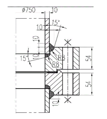
Figure 1
1.2 The welding of flanges and cylinders
Prepare the finished flange according to the process. Assemble the joint between the flange and the cylinder body according to the requirements of the drawings. Manually weld the welding seam between the cylinder body and the flange. Carry out dimension inspection. Process the sealing surface of the flange according to the technical requirements.
1.3 Welding process parameters of the flange and cylinder
The welding parameters of the bottom layer, intermediate layer and surface layer of the welding seam are shown in the following table:
In the manufacture of pressure vessels, if effective measures for deformation are not taken before welding between the large-diameter slip-on flange and the cylinder body, post-weld deformation is likely to occur, and the repair is time-consuming and laborious, which causes waste of material resources and difficult repair. If the deformation cannot be fixed, it will cause certain economic losses to the enterprise. Take the deformation caused by welding between the slip-on flange of the distillation column manufactured by a company and the cylinder as an example, the cause of the deformation is analyzed.
1. The description of the case
1.1 Basic parameters of the distillation column
Design pressure: 0.4MPa(F.V)
Design temperature: 300°C
Nominal diameter: 750mm
The thickness of the cylinder:10mm
The material of the main pressure component: the flange is made from ASME SA182-F304L and solid solution and the cylinder is made from ASME SA240-304L-solid solution. The welding structure between the equipment flange and the cylinder is shown in Figure 1.
Figure 1
1.2 The welding of flanges and cylinders
Prepare the finished flange according to the process. Assemble the joint between the flange and the cylinder body according to the requirements of the drawings. Manually weld the welding seam between the cylinder body and the flange. Carry out dimension inspection. Process the sealing surface of the flange according to the technical requirements.
1.3 Welding process parameters of the flange and cylinder
The welding parameters of the bottom layer, intermediate layer and surface layer of the welding seam are shown in the following table:
| Welding layers | Welding methods | Filler metal | Current Polarity | Current range | Voltage range | Welding speed range cm/min. | ||
| Standard | Type | Diameter | ||||||
| The first, second and third layers | SMAW | AWS A5.4 | E308-16 |
Φ4.0 | DCEP | 140 to 160A |
22 to 28A |
15 to 25 |
1.4 Post-welding inspection
After the welding of the flange and the cylinder is completed, the inspector checked the size of the flange, and deformation occurred due to welding for the flange; the flange sealing surface inclined towards the outside of the flange; the deformation shaped like a horn happened for the entire flange (Figure 2).
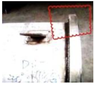
Figure 2
The analysis results of the final measurement data are shown in the following table:
| Measuring angles | The inner diameter deviation of the upper end face of the flange/±0.8mm | The outer diameter deviation of the flange/±0.8mm | The diameter deviation of the flange bolt hole center circle/±0.8mm | The diameter deviation of the outer circle of the boss of the flange sealing surface/-0.9mm to 0mm |
| 0°&180° | +2.4 | +3.0 | +2.8 | +2.9 |
| 45°&225° | +2.3 | +3.2 | +2.9 | +2.4 |
| 90°&270° | +2.2 | +2.9 | +2.6 | +2.7 |
| 135°&315° | +2.4 | +3.0 | +2.7 | +2.5 |
After analyzing the data in the above table, the deformation caused by welding of the outer diameter of the flange is quite different from the standard value, and the inner diameter of the flange has little influence. However, from the inspection results, the deformation after welding is different from the maximum size deviation required by the standard. far. Since the deformation of the flange has exceeded the machining allowance given by normal manufacturing, it cannot be corrected by machining. The flange is scrapped.
2. The analysis of welding variation
2.1 Properties of the material
304L is a variant of 304 austenitic stainless steel with a lower carbon content, that is, ultra-low carbon stainless steel. Great deformation caused by shrinkage and residual stress in the welding process easily occurs due to the material's excellent fracture toughness, corrosion resistance, higher coefficient of thermal expansion and lower coefficient of thermal conductivity.
2.2 Manufacturing processes
When welding is performed, the operator did not perform restraint tooling for the flange to prevent welding deformation. For the welding structure between the flange and the cylinder, it is not easy to control the deformation caused by welding without restraining tooling. The welding structure can be approximated as a single-sided continuous welding. The axially heated part of the welding seam area is affected by the hoop shrinkage stress when the welding seam is cooled, and the overall temperature of the flange also varies with the distance from the heat-affected zone of the welding seam. The farther the distance is, the lower the temperature and the greater the rigidity become; it is easy to make the lower end of the flange shrink towards the central shaft in the circumferential direction, resulting in angular deformation.
In addition, welding operators fail to strictly follow the manufacturing process procedures and welding parameters to perform welding operations. They often weld workpieces based on welding experience and operating habits alone. Therefore, it directly affects the quality of welding to a large extent.

Related News
- Failure Analysis of Cracking in a 16MnⅢ Weld Neck Flange
- ANSYS Analysis for Anchor Flange Structural Optimization
- Flange Leakage in Hydrogen-Cooled Pipeline Systems of Thermal Power Plants
- Flange Sealing Technology and Installation Method for Hydrogenation Units
- Multi-Directional Die Forging Process for Horizontal Valve Bodies with Dual Flanges
- Structural Performance Analysis of Zirconium Pressure Vessel Lap Joint Flanges
- Low-Temperature Flange Sealing Solutions for Cryogenic Chemical Pipelines
- Innovative Technology for Automatic Alignment in Underwater Flange Assembly
- Stamped Steel Slip-On Flanges
- Design and Finite Element Analysis of Anchor Flanges for Oil & Gas Pipelines