Electric Arc Materials Adding for Nuclear Grade Flanges (Part Two)
(2) Microstructure
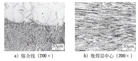
After the arc additive TIG surfacing of the flange simulation part is completed, the metallographic samples are ground from the fusion line and the center of the surfacing layer respectively, and they are etched with ferric chloride plus hydrochloric acid solution. Observe the microstructure with the metallographic microscope according to RCC-MSI400 (Figure 3). Welding defects such as cracks, lack of welding, lack of fusion, and gas holes in the surfacing layer were not found after observing. The fusion of surfacing layer and base metal is good. No microcracks and deposits were found. The base metal and surfacing layer have a typical austenite structure.
(3) Mechanical properties
According to the standard RC CM2000 and 2002 addendum, a longitudinal tensile test is performed for the cladding metal in the center of the surfacing layer at room temperature and 350℃. The results are shown in Table 3. It can be seen from Table 3 that the yield strength, tensile strength and elongation after fracture at room temperatures and high temperatures all meet the requirements. At the same time, two surface bend and one side bend specimens were taken at the center of the surfacing layer and the bending test was conducted according to GB/T 232-2010 Bending Test Methods for Metallic Materials. The test standard was in accordance with RCCM2000 plus 2002 addendum, and the test result showed no defects.
(4) Impact performance
According to the standard GB/T 229-2007 Charpy Pendulum Impact Test Methods for Metallic Materials, the samples were subjected to an impact test at room temperatures, and three impact samples were taken from the surface, center, root and heat-affected zone of the surfacing layer. Carry out impact tests. The size of the sample is 55mm x 10mm x 10mm. Took the average of the test results of each group, and the results were shown in Table 4. The impact absorption energy is much higher than the standard requirement, and it has a good toughness reserve.
Table 3 Mechanical properties of surfacing layers
| Items | Test values | RCCM2000 Standard plus 2002 addendum | ||
| Room temperatures | 350℃ | Room temperatures | 350℃ | |
| Yield strength/MPa | 518 | 418 | Greater than and equal to 210 | Greater than and equal to 140 |
| Tensile strength/MPa | 597 | _ | Between 520 and 670 | _ |
| Elongation after fracture (%) | 31 | _ | Greater than and equal to 30 | _ |
Table 4 Impact performance of surfacing layers
| Items | Impact absorption energy of surfacing layers/J | |||
| Surfaces | Centers | Roots | Heat affected zones | |
| Test values | 132.7 | 136.7 | 133.0 | 215.0 |
| Standard RCCM2000 plus 2002 addendum | Greater than and equal to 60 |
_ | ||
(5) Stress tests
According to the stress measurement results, the end surface of the surfacing layer and the outer wall pipe of the simulated part was in a stretched state after the surfacing is completed, as shown in Figure 4. After the surfacing with 14mm, the maximum stress on the end face of the surfacing layer of the simulated part was about 275MPa; the axial stress of heat effect zone of the outer wall surfacing layer was about 280MPa, which was much lower than the yield strength of the material. The stress on the outer wall of the simulated part is decreasing in the area away from the surfacing layer, and then the stress rises approaching the butt welding seam of the outer wall. The maximum circumferential and axial stress appears near the butt welding seam of the outer wall, which is about 320MPa, indicating that residual stress generated by the butt welding seam was superimposed on that of the surfacing layer. After the flange has been operated for a long time, the residual stress of the butt welding seam on the outer wall was effectively released. Therefore, after the surfacing of the flange end face was completed, there was no need to consider the residual stress of the butt welding seam.
Figure 4 Stress test results
4. On-site implementation
(1) Cleaning and inspection of defective areas
A large amount of grinding is required due to the serious damage to the flange surface and the great defect depth. At the same time, considering the radiation dose factor, a beveling machine was used to cut the depth of 10 to 20mm, and then an angle grinder was used to grind the damaged part of the flange. Completely removed the corroded part (Figure 5). After the grinding was completed, the liquid penetration test was performed on the surface, and the next process was carried out after the product was qualified.
Figure 5 Arc material adding processes of flange surfaces
(2) Manual ITIG surfacing
After the liquid penetration test was qualified, manual TIG filler wire welding was used to perform partial surfacing on the damaged flange surface, and the deeper parts were leveled and polished to prepare for arc additive TIG surfacing. In the entire surfacing process, the interlayer temperature was less than 150℃, and at the same time, pay attention to the radiation dose to the personnel to avoid exceeding the standard.
(3) Arc additive TIG surfacing
After the manual TIG surfacing was completed, installed the arc material adding equipment to the required part through simple tooling, and realized the remote control of the equipment and the observation of the welding process through the remote controller and the visual monitoring system. In the entire arc additive TIG surfacing process, controlled the interlayer temperature to be less than 150℃, and repeated the surfacing until the surfacing layer exceeded the original flange size by 1 to 2mm.
(4) Cutting and inspection after surfacing
After the arc additive TIG surfacing was completed, the equipment was removed, and the excess part was cut by a beveling machine to reach the original design size of the flange; the liquid penetration test was carried out.
5. Conclusion
1) By selecting the appropriate surfacing welding process and method, the arc material adding of the simulation part of the pipe end flange surface was successfully realized. The chemical composition, microstructure, mechanical performance test and stress test results of the surfacing layer all showed that the arc material adding process was stable and reliable, and met the requirements of the flange surface's surfacing repair.
2) Through reasonable control of heat input, the calculated value of δ ferrite of the surfacing layer met the requirements of the standard, which could effectively prevent and reduce the generation of welding hot cracks, and could improve the resistance to intergranular corrosion of the welding seam. The energy value of impact absorption of the surfacing layer exceeded 130J, and the margin was great. The stress generated by the surfacing layer was small, and the stress generated on the end face of the flange surfacing layer was about 275MPa, which was much lower than the yield strength of the material.
3) The effective implementation of the online arc material adding process of the pipe end flange surface has become a reliable means to solve the damage of the nuclear power flange on site. Compared with replacement or manual repair of the flange, the arc additive TIG surfacing process can not only ensure the surfacing quality of the flange surface, but also improve the efficiency of repair on site and reduce the radiation dose to personnel.

Related News
- Failure Analysis of Cracking in a 16MnⅢ Weld Neck Flange
- ANSYS Analysis for Anchor Flange Structural Optimization
- Flange Leakage in Hydrogen-Cooled Pipeline Systems of Thermal Power Plants
- Flange Sealing Technology and Installation Method for Hydrogenation Units
- Multi-Directional Die Forging Process for Horizontal Valve Bodies with Dual Flanges
- Structural Performance Analysis of Zirconium Pressure Vessel Lap Joint Flanges
- Low-Temperature Flange Sealing Solutions for Cryogenic Chemical Pipelines
- Innovative Technology for Automatic Alignment in Underwater Flange Assembly
- Stamped Steel Slip-On Flanges
- Design and Finite Element Analysis of Anchor Flanges for Oil & Gas Pipelines