Electric Arc Materials Adding for Nuclear Grade Flanges (Part One)
Abstract: According to the corrosion status of the flange surface of a certain pipe end of a nuclear power plant and the site construction conditions, the method of arc materials adding of the flange surface was studied. Through the demonstration and analysis of the arc surfacing test of the flange's simulation part, the result showed that the performance of the flange surface's surfacing layer adopting the arc material adding met the requirements for nuclear power design standards. The effective implementation of the online arc material adding process of the pipe end's flange surface has become a reliable method to solve the defect of the flange on site. Compared with replacement or manual repair of the flange, the arc material adding TIG surfacing process can not only ensure the surfacing quality of the flange surface, but also improve the efficiency of on-site repair and reduce the radiation dose of personnel.
1. Introduction
The safety injection system is an important special safety facility for pressurized water reactor nuclear power plants. In the event of a loss of water in the reactor coolant system, the reactor core is kept submerged with water to prevent the fuel cladding from melting; when a pipeline breaks in the main steam system, quickly inject concentrated boron solutions to shut down the reactor quickly and safely and prevent the reactor from returning to criticality.
A flange is an important component in the pipeline engineering of nuclear power plants. It is mainly used for the connection between pipelines, pumps and valves. It plays a vital role in the safety of the system. The main form of its failure is corrosion.
During the overhaul of a nuclear power plant, when the safety injection system was checked, it was found that there was severe corrosion on the flange surface of a certain pipe end; the maximum corrosion depth reached 14 mm, as shown in Figure 1. Because the flange and the pipeline were welded, it is difficult to remove them on site. Moreover, the repair workload and the radiation were much. Compared with the overall replacement or manual welding repair, the corroded flange surface subjected to online arc material adding would greatly reduce the maintenance periods and costs.
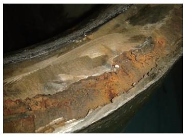
Figure 1 Corrosion of the flange surface
Arc material adding technology is a technology that adopts the principle of layer-by-layer cladding, and uses the arc generated by welding machines such as molten inert gas welding (MIG) or tungsten inert gas welding (TIG) as the heat source. Through the addition of wires, advanced digital manufacturing technology of metal parts is gradually formed under the control of the program. This technology not only has the advantages of high deposition efficiency and high wire utilization, but also has the ability of in-situ composite manufacturing and forming large-size parts.
Aiming at the corrosion of the flange surface of the pipe end, the development and performance verification of the arc material adding manufacturing process using TIG as the heat source were carried out on the simulation body to obtain a reliable repair process. The damaged part of the flange was repaired online by the arc material adding manufacturing. Through the reasonable selection of surfacing materials and the correct formulation of the process, the damaged surface of the flange was successfully repaired; the service life of the flange was increased, and significant economic benefits were achieved.
2. Materials and methods of simulated tests
The pipe end's flange surface mentioned in this article was a part of the low-pressure safety injection pump. The safety level is RCC-P2 and the manufacturing level is RCC-M2. Its structure is similar to the butt welding neck flange, and has two inner and outer welding ends. The flange material is Z2CN18.10. According to the design drawings and on-site corrosion conditions, the pipe end's flange simulation parts were made, as shown in Figure 2.
First, manual TIG filler wire welding was used to perform bottoming surfacing on the flange surface before repair; second, Liburdi GT-VI equipment was used for arc material adding. The equipment has functions such as remote control, arc voltage control and visual monitoring, which can ensure the formation and quality control of the entire surfacing process. The surfacing materials and process parameters are shown in Table 1. In the surfacing welding process, the temperature between layers was controlled to be less than 150℃; after each layer was welded, observed the surface quality of the surfacing layer until it reached 14 mm. There were 7 layers.
After the flange's surfacing was completed, X-ray diffraction (XRD) was used to perform stress testing on key positions. A set of measuring points were located on the end face of the surfacing layer of the simulated part, and the other was located on the outer wall of the simulated part. Before the test, the electrolytic method was used to polish the measuring point area to eliminate additional stress.
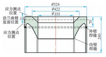
Figure 2 The structure of the flange of the simulated part
After the arc material adding TIG surfacing of the entire flange surface was completed, various samples were prepared according to the standard RCCM2000 and 2002 addendum, and chemical composition inspection, microstructure observation, mechanical property tests were carried out to evaluate the performance of the surfacing process.
3. The results and analysis of simulated tests
(1) Component analysis
There was a certain amount of ferrite in the ER316L surfacing layer, which could not only effectively prevent and reduce welding hot cracks, but also improve the resistance to intergranular corrosion of the welding seam. However, δ phase ferrite will precipitate σ phase and cause embrittlement of the weld metal at high temperatures. Therefore, the ferrite content in the weld must be controlled. In accordance with the testing standard GB/T 11170-2008 Testing Multi-element Content in Stainless Steel Spectrometry for Spark Discharge Atomic Emission, the chemical composition of the surfacing layer of the simulated body was tested. The results were shown in Table 2. It can be seen from the test results that the content of each element and the calculated value of δ ferrite fully met the requirements of the standard RCCM2000 and 2002 addendum.
Table 1 Surfacing materials and process parameters
1. Introduction
The safety injection system is an important special safety facility for pressurized water reactor nuclear power plants. In the event of a loss of water in the reactor coolant system, the reactor core is kept submerged with water to prevent the fuel cladding from melting; when a pipeline breaks in the main steam system, quickly inject concentrated boron solutions to shut down the reactor quickly and safely and prevent the reactor from returning to criticality.
A flange is an important component in the pipeline engineering of nuclear power plants. It is mainly used for the connection between pipelines, pumps and valves. It plays a vital role in the safety of the system. The main form of its failure is corrosion.
During the overhaul of a nuclear power plant, when the safety injection system was checked, it was found that there was severe corrosion on the flange surface of a certain pipe end; the maximum corrosion depth reached 14 mm, as shown in Figure 1. Because the flange and the pipeline were welded, it is difficult to remove them on site. Moreover, the repair workload and the radiation were much. Compared with the overall replacement or manual welding repair, the corroded flange surface subjected to online arc material adding would greatly reduce the maintenance periods and costs.
Figure 1 Corrosion of the flange surface
Arc material adding technology is a technology that adopts the principle of layer-by-layer cladding, and uses the arc generated by welding machines such as molten inert gas welding (MIG) or tungsten inert gas welding (TIG) as the heat source. Through the addition of wires, advanced digital manufacturing technology of metal parts is gradually formed under the control of the program. This technology not only has the advantages of high deposition efficiency and high wire utilization, but also has the ability of in-situ composite manufacturing and forming large-size parts.
Aiming at the corrosion of the flange surface of the pipe end, the development and performance verification of the arc material adding manufacturing process using TIG as the heat source were carried out on the simulation body to obtain a reliable repair process. The damaged part of the flange was repaired online by the arc material adding manufacturing. Through the reasonable selection of surfacing materials and the correct formulation of the process, the damaged surface of the flange was successfully repaired; the service life of the flange was increased, and significant economic benefits were achieved.
2. Materials and methods of simulated tests
The pipe end's flange surface mentioned in this article was a part of the low-pressure safety injection pump. The safety level is RCC-P2 and the manufacturing level is RCC-M2. Its structure is similar to the butt welding neck flange, and has two inner and outer welding ends. The flange material is Z2CN18.10. According to the design drawings and on-site corrosion conditions, the pipe end's flange simulation parts were made, as shown in Figure 2.
First, manual TIG filler wire welding was used to perform bottoming surfacing on the flange surface before repair; second, Liburdi GT-VI equipment was used for arc material adding. The equipment has functions such as remote control, arc voltage control and visual monitoring, which can ensure the formation and quality control of the entire surfacing process. The surfacing materials and process parameters are shown in Table 1. In the surfacing welding process, the temperature between layers was controlled to be less than 150℃; after each layer was welded, observed the surface quality of the surfacing layer until it reached 14 mm. There were 7 layers.
After the flange's surfacing was completed, X-ray diffraction (XRD) was used to perform stress testing on key positions. A set of measuring points were located on the end face of the surfacing layer of the simulated part, and the other was located on the outer wall of the simulated part. Before the test, the electrolytic method was used to polish the measuring point area to eliminate additional stress.
Figure 2 The structure of the flange of the simulated part
After the arc material adding TIG surfacing of the entire flange surface was completed, various samples were prepared according to the standard RCCM2000 and 2002 addendum, and chemical composition inspection, microstructure observation, mechanical property tests were carried out to evaluate the performance of the surfacing process.
3. The results and analysis of simulated tests
(1) Component analysis
There was a certain amount of ferrite in the ER316L surfacing layer, which could not only effectively prevent and reduce welding hot cracks, but also improve the resistance to intergranular corrosion of the welding seam. However, δ phase ferrite will precipitate σ phase and cause embrittlement of the weld metal at high temperatures. Therefore, the ferrite content in the weld must be controlled. In accordance with the testing standard GB/T 11170-2008 Testing Multi-element Content in Stainless Steel Spectrometry for Spark Discharge Atomic Emission, the chemical composition of the surfacing layer of the simulated body was tested. The results were shown in Table 2. It can be seen from the test results that the content of each element and the calculated value of δ ferrite fully met the requirements of the standard RCCM2000 and 2002 addendum.
Table 1 Surfacing materials and process parameters
| Methods | Welding materials | Diameters of welding materials/mm | Welding currents/A | Arc voltage/V | Welding speeds/mm-min-1 | Argon flow/L.min-1 | |
| Peak values | Base values | ||||||
| Manual ITIG surfacing | ER316L | 1.6 | From 120 to 180 | _ | _ | _ | From 8 to 15 |
| Arc material adding TIG surfacing | ER316L | 0.8 | From 180 to 260 | From 100 to 180 | From 9 to 13 | From 70 to 90 | From 15 to 30 |
Table 2 The chemical composition (mass fraction) of welded metal (%)
| Elements | C | Si | Mn | S | P | Cr | Ni | Mo | Calculated values of δ ferrite |
| Test values | 0.010 | 0.43 | 1.75 | 0.012 | 0.016 | 18.59 | 12.16 | 2.67 | 10.6 |
| Standard requirements | Less than and equal to 0.030 | Less than and equal to 1.00 | From 1.00 to 2.50 | Less than and equal to 0.030 | Less than and equal to 0.030 | From 17.00 to 20.00 | From 10.00 to 13.00 | From 2.00 to 3.00 | From 5 to 15 |

Related News
- Failure Analysis of Cracking in a 16MnⅢ Weld Neck Flange
- ANSYS Analysis for Anchor Flange Structural Optimization
- Flange Leakage in Hydrogen-Cooled Pipeline Systems of Thermal Power Plants
- Flange Sealing Technology and Installation Method for Hydrogenation Units
- Multi-Directional Die Forging Process for Horizontal Valve Bodies with Dual Flanges
- Structural Performance Analysis of Zirconium Pressure Vessel Lap Joint Flanges
- Low-Temperature Flange Sealing Solutions for Cryogenic Chemical Pipelines
- Innovative Technology for Automatic Alignment in Underwater Flange Assembly
- Stamped Steel Slip-On Flanges
- Design and Finite Element Analysis of Anchor Flanges for Oil & Gas Pipelines