Failure and Crack Analysis of an EO/EG Unit Tower Inlet Flange
Abstract: A flange on the feed line of the ethylene glycol dehydration tower in the EO/EG unit of a petrochemical plant experienced fracture failure. To identify the cause of the failure, a comprehensive analysis was conducted, including macroscopic observation, hardness testing, chemical composition analysis, mechanical property testing, metallographic examination, scanning electron microscopy (SEM), and energy-dispersive spectroscopy (EDS). The results revealed that the flange failure resulted from chloride-induced stress corrosion fatigue cracking. The crack initiated at stress concentration sites on the inner wall surface—such as machining marks, grinding indentations, and weld spatters—and propagated outward under alternating loads and chloride-induced stress corrosion until it penetrated the wall, resulting in leakage.
It is therefore essential to strengthen manufacturing and installation quality control and to limit the chloride ion content in the process medium to ensure safe operation of the flange. Ethylene oxide (EO) and ethylene glycol (EG) are key raw materials in the chemical industry, widely used in the production of plastics, polyester fibers, antifreeze, and various other products. In an EO/EG unit, ethylene is oxidized to produce ethylene oxide, which is subsequently hydrolyzed to form ethylene glycol. In piping systems, flanges serve as critical components for connecting and sealing pipe sections and equipment. They enable easy disassembly and reassembly, facilitating inspection, maintenance, and cleaning. During repairs or replacements, a flange can be removed locally without dismantling the entire pipeline, enhancing operational flexibility and maintenance efficiency. Depending on the properties of the process medium, flanges are typically manufactured from corrosion-resistant materials such as stainless steel or alloy steel. In highly corrosive environments, protective coatings are often applied to extend their service life. As essential connecting and sealing components, flanges have long been a key focus of reliability research. Failures can result from sealing degradation, including gasket aging or bolt loosening and damage. To address these issues, researchers are developing new high-temperature, corrosion-resistant sealing materials. Additionally, chemical corrosion of flanges and bolts has prompted the development of advanced alloys and protective anti-corrosion coatings. In addition, mechanical stresses can cause bolt breakage or flange deformation. These issues can be mitigated through optimized design and finite element analysis to enhance structural integrity. Temperature fluctuations can induce thermal expansion or contraction, resulting in flange distortion. Therefore, enhancing thermal stress resistance is equally important. In EO/EG units, the design, material selection, and maintenance of flanges directly influence the operational safety and efficiency of the system. Although flange failures still occur in practice, ongoing research and technological advancements have significantly enhanced their performance. With the ongoing adoption of new materials and technologies, the reliability and service life of flanges are expected to improve further. This study focuses on the flange of the ethylene glycol dehydration tower feed line in an EO/EG unit at a petrochemical plant. Failed samples were collected and subjected to a comprehensive analysis, including macroscopic observation, hardness testing, chemical composition and mechanical property evaluation, metallographic examination, scanning electron microscopy (SEM), and energy-dispersive spectroscopy (EDS). The mechanisms of crack initiation and propagation were identified, and measures to prevent recurrence were proposed.
The EO/EG unit was completed and commissioned in 2020. In late July 2023, Chemical Department III of Sinopec (Guangdong) Refining & Chemical Co., Ltd. discovered a crack in the flange on the feed line of the ethylene glycol dehydration tower (T405) of the EO/EG unit, after roughly 2 years and 10 months of operation. The flange material is ASTM A182 F304, with a specification of DN200 CL150. The process medium in the pipeline is ethylene glycol, drawn from the bottom of T404 (Ethylene Glycol Concentration Tower 4). The system operates at slightly positive pressure and a normal temperature of 180 °C.
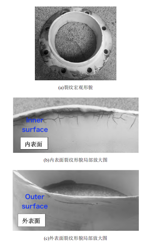
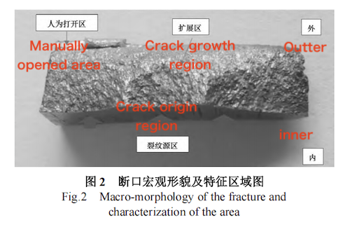
As shown in Figure 1, multiple cracks were observed on both the inner and outer surfaces of the flange. Notably, prominent cracks were distributed circumferentially around the base metal near the inner-surface weld. Some cracks were located within the heat-affected zone (HAZ), while others extended beyond it. The cracks propagated in both circumferential and longitudinal directions. The circumferential cracks consisted of multiple short, stepped segments, whereas the longitudinal cracks terminated sharply. All cracks originated from the inner surface of the flange, with most not yet fully penetrating the pipe wall. An additional crack was observed on a weld spatter on the inner surface, away from the main weld seam. This crack originated at the weld spatter and extended into the adjacent base metal, without fully penetrating the pipe wall. To further investigate the fracture morphology, a representative crack was selected and deliberately opened. Figure 2 shows the macroscopic appearance of the fracture surface. The dark-yellow region corresponds to the pre-existing fracture surface, while the grayish-white area represents the artificially opened portion. The pre-existing fracture surface is smooth and devoid of noticeable plastic deformation or shear lips, indicating a brittle fracture mode. Rolling marks and fatigue striations are also visible, indicating features typical of fatigue failure. The crack initiated on the inner wall of the flange, and radial patterns radiating from the initiation site suggest multiple origins, consistent with a multi-site initiation mechanism. Based on these macroscopic features, it is preliminarily inferred that the cracks are fatigue-related, likely originating from surface imperfections—such as machining marks, grinding indentations, or weld spatters—on the inner flange surface and may have been exacerbated by chloride-induced stress corrosion.

(a) Macroscopic morphology of the crack on the inner surface (b) Magnified view of the crack morphology on the inner surface
(c) Magnified view of the crack morphology on the outer surface
Figure 1 Macroscopic morphology of the flange crack

Figure 2 Macroscopic morphology of the fracture surface and characterization of different regions
Hardness testing was conducted on samples taken from regions of the flange both near and away from the crack. Following the national standard SH/T 3408-2012, “Petrochemical Steel Butt-Welded Pipe Fittings,” measurements were taken at five points on each sample. The results are summarized in Table 1. The data indicate that the hardness values of the flange, both near and away from the crack, are similar and meet the hardness requirements specified for ASTM A182 F304 material.
Table 1 Hardness Test Results
|
Test Location |
Measurement Points (HBW) |
Standard Value (HBW) |
|
Far from crack |
161, 158, 160 |
≤ 201 |
|
Near crack |
150, 153, 162, 160 |
≤ 201 |
Chemical composition analysis was conducted on samples taken from the flange material, with the results shown in Table 2. The measured composition meets the chemical requirements of ASTM A182 F304, confirming that the material complies with the specified standards.
Table 2 Chemical Composition Analysis Results (wt%)
|
Element |
Test Result (A182 F304) |
Standard Requirement (A182 F304) |
A182 F304L |
A182 F304H |
|
C |
0.05 |
≤ 0.08 |
≤ 0.03 |
0.04–0.10 |
|
Si |
0.42 |
≤ 1.00 |
≤ 1.00 |
≤ 1.00 |
|
Mn |
1.14 |
≤ 2.00 |
≤ 2.00 |
≤ 2.00 |
|
P |
0.035 |
≤ 0.045 |
≤ 0.045 |
≤ 0.045 |
|
S |
0.001 |
≤ 0.030 |
≤ 0.030 |
≤ 0.030 |
|
Cr |
18.43 |
18.0–20.0 |
18.0–20.0 |
18.0–20.0 |
|
Ni |
8.28 |
8.0–11.0 |
8.0–11.0 |
8.0–11.0 |
Tensile and impact tests were performed at room temperature on samples taken from the flange. The results are summarized in Table 3. The measured tensile strength, yield strength, and elongation after fracture all meet the ASTM A182 F304 requirements. The high impact energy further confirms that the material exhibits the expected toughness of austenitic stainless steel.
Table 3 Mechanical Property Test Results
|
Property |
Test Result |
ASTM A182 F304 Requirement |
|
Tensile Strength (MPa) |
583 |
≥ 515 |
|
Yield Strength (MPa) |
312 |
≥ 205 |
|
Elongation (%) |
64 |
≥ 30 |
|
Impact Energy (J) |
180 |
— |
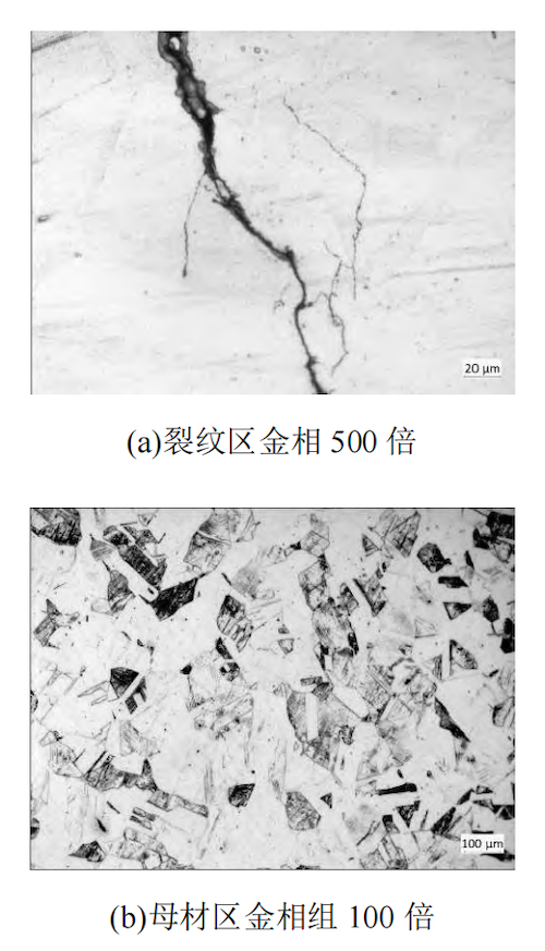
Samples were taken from both the cracked region and areas away from the crack for metallographic analysis. The microstructure of the cracked region is shown in Figure 3(a). The crack originates from a surface pit on the inner wall of the flange base metal and propagates through the material. The main crack is relatively straight, exhibiting typical characteristics of fatigue cracking. However, branching occurs along the propagation path and near the crack tip, where corrosion products have accumulated, indicating characteristics of stress corrosion cracking (SCC). Therefore, the fracture is inferred to be due to stress corrosion fatigue cracking. The metallographic structure of the base metal away from the crack is shown in Figure 3(b). The microstructure is fully austenitic, with an average grain size of approximately 5–6 according to the ASTM grain size number. Energy-dispersive spectroscopy (EDS) analysis using scanning electron microscopy (SEM) revealed a high concentration of chlorine (Cl) in the corrosion products at the crack tip, with a maximum Cl content of 0.35 wt.%, confirming chloride-induced corrosion.

(a) Metallographic structure of the crack zone (500×) (b) Metallographic structure of the base metal zone (100×)
Figure 3 Metallographic structure of the flange sample
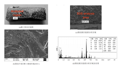
To further investigate the crack initiation mechanism and characteristics, the fracture surface was examined using scanning electron microscopy (SEM). The fracture feature region is shown in Figure 4(a). The fracture surface is smooth and flat, with clearly visible rolling marks and fatigue striations under high magnification. Figure 4(b) shows the microstructure of the crack propagation zone. The crack initiated on the inner surface of the flange, with distinct radial striations radiating from the crack origin. Figure 4(c) highlights the area selected for energy-dispersive spectroscopy (EDS) analysis, and Figure 4(d) presents the corresponding EDS results. The analysis revealed a high chloride concentration at the crack initiation site, with a measured Cl content of 0.38 wt.%. Based on the fracture surface microstructure and EDS analysis, the following conclusions can be drawn: Rolling marks and fatigue striations are present throughout the crack initiation zone, propagation zone, and crack tip, indicating that fatigue was a primary mechanism driving both crack initiation and growth. High chlorine concentrations were detected in both the crack initiation and crack tip regions, indicating that chloride-induced stress corrosion cracking (SCC) also played a role in crack propagation. In summary, the flange crack resulted from stress corrosion fatigue, initiating on the inner wall surface of the flange.

Figure 4 Fracture surface characteristic region
(a) Overall fracture morphology (500×) (b) Microstructure of the crack propagation zone (500×) (c) EDS analysis area of the crack initiation zone (d) EDS analysis area and results of the crack initiation zone
Macroscopic examination revealed the presence of multiple cracks on both the inner and outer surfaces of the flange. Distinct circumferential cracks were observed around the full circumference of the base metal near the inner-surface weld. Another crack was identified on a weld spatter formed during welding, as well as in the adjacent base material, located far from the main weld seam. No cracks were detected in the circumferential weld itself. Some cracks in the base material near the weld were situated within the heat-affected zone (HAZ), while others extended beyond it. The cracks propagated in both circumferential and longitudinal directions. The circumferential cracks comprised multiple short, stepped segments, suggesting multi-site initiation. Most of the circumferential and longitudinal cracks had not penetrated the pipe wall, indicating that crack initiation originated on the inner surface of the flange. The fracture surfaces were smooth, lacking noticeable plastic deformation or shear lips, indicating brittle fracture behavior. Rolling marks and fatigue striations were observed, with radial patterns radiating from multiple initiation sites, confirming that the cracks were multi-origin fatigue cracks starting from the inner surface. Based on the overall macroscopic morphology, the cracks are preliminarily identified as fatigue or stress corrosion fatigue cracks, originating from machining marks, grinding indentations, and weld spatters on the inner surface of the flange.
The chemical composition analysis indicates that the flange material meets the requirements specified for ASTM A182 F304 stainless steel.
The measured hardness values at locations both near and away from the cracks were consistent and met the hardness requirements for F304 stainless steel.
Tests indicate that the flange material’s tensile strength, yield strength, and elongation after fracture all meet the requirements of ASTM A182 F304. Additionally, the impact energy is sufficiently high, confirming compliance with austenitic stainless steel standards.
The examination shows that the crack initiated from a pit or weld spatter on the inner wall of the flange base material and propagated through the surrounding section. The main crack is relatively straight, exhibiting typical fatigue crack features, but it branches during propagation and at the crack tip. Corrosion products are present within the crack, with those at the crack tip containing a high chlorine concentration (up to 0.35 wt%), displaying characteristics typical of stress corrosion cracking. Therefore, the crack is concluded to be a stress corrosion fatigue crack. The metallographic structure of the flange base material is austenitic, with an average grain size of approximately 5–6 (ASTM grain size number).
(6) Microscopic examination of the fracture surface reveals rolling marks and fatigue striations throughout the crack initiation zone, propagation zone, and fracture tip, confirming that fatigue was the dominant mechanism driving crack initiation and propagation. Elevated chlorine (Cl) levels were detected in both the crack initiation and tip regions, further indicating that chloride stress corrosion cracking contributed to crack propagation. Therefore, it is concluded that the flange crack originated as a stress corrosion fatigue crack on the inner wall surface. Based on the above analysis, the flange crack is confirmed to be a stress corrosion fatigue crack. The crack initiated at stress concentration points on the inner wall surface—such as machining marks, grinding indentations, and weld spatters—and propagated outward under alternating loads and chloride-induced stress corrosion until it fully penetrated the wall, causing leakage.
The primary causes of stress corrosion and fatigue cracking in this flange are as follows:
(1) The alternating load is generated by fluid-induced vibration within the pipeline. The aqueous ethylene glycol discharged from the bottom of T404 is depressurized by the control valve, forming a vapor–liquid two-phase flow. After further acceleration through the flow-limiting orifice plate, additional vaporization occurs at the cracked flange location, creating localized vortices that cause pipeline vibration and generate alternating mechanical loads.
(2) As the fluid accelerates through the flow-limiting orifice plate, secondary vaporization occurs at the cracked flange, leading to alternating wet and dry conditions. This environment promotes the accumulation of chloride ions at stress concentration sites—such as machining marks, grinding indentations, and weld spatters—on the inner surface of the flange, leading to the formation of localized high-chloride zones.
(3) The flange material complies with ASTM A182, “Forged or Rolled Alloy-Steel Pipe Flanges, Forged Fittings, and Valves and Parts for High-Temperature Service.” The base material exhibits an austenitic grain size of approximately ASTM grain size number 5–6, indicating a coarse-grained structure. Although the material meets the ASTM A182 standard requirements, its relatively high carbon content (0.05 wt%) and coarse-grained microstructure diminish its resistance to chloride-induced corrosion, increasing its susceptibility to pitting and stress corrosion cracking.
Therefore, the primary causes of stress corrosion and fatigue cracking in the flange are summarized as follows:
- The material’s high carbon content and coarse-grained structure reduce its resistance to chloride-induced corrosion, making it more susceptible to pitting and stress corrosion cracking.
- The inner surface of the flange features stress concentration defects—such as machining marks, grinding indentations, and weld spatters—that act as crack initiation sites under alternating loads and corrosive conditions.
This study focused on the flange of the ethylene glycol dehydration tower feed line in the EO/EG unit at Sinopec Refining & Chemical Co., Ltd. Samples of the failed flange were collected and subjected to comprehensive analysis, including macroscopic observation, hardness testing, chemical composition and mechanical property evaluation, metallographic examination, scanning electron microscopy (SEM), and energy-dispersive spectroscopy (EDS).
Conclusions and Recommendations
The flange failure was caused by chloride-induced stress corrosion fatigue cracking. The crack initiated at stress concentration points on the inner wall surface—such as machining marks, grinding indentations, and weld spatters—and propagated outward under alternating loads combined with chloride stress corrosion, eventually penetrating the flange wall and causing leakage. The primary causes of chloride-induced stress corrosion and fatigue cracking in this flange are as follows:
- The high carbon content and coarse-grained microstructure of the material reduced its resistance to chloride corrosion, increasing susceptibility to pitting and stress corrosion cracking. It is recommended to regularly monitor and control the chloride ion concentration in the process medium.
- Defects on the inner surface—including machining marks, grinding indentations, and weld spatters—served as stress concentration sites, promoting crack initiation. It is recommended to fabricate the flange from 304L or 316L stainless steel with a grain size of grade 8 or finer, and to strengthen quality control during manufacturing and installation to eliminate surface defects on both the inner and outer walls of the flange.
Related News
- Structural Design and Strength Analysis of a Deepwater Riser Suspension Flange
- Analysis of Heat Dissipation Losses in High-Temperature Flanges and Pipelines Used in Oil Refineries
- Failure and Crack Analysis of an EO/EG Unit Tower Inlet Flange
- Pipe Flange Bolt Tightening in LNG Projects: Key Considerations
- Ultrasonic Testing of High-Neck Flange Welds
- Underwater Flange Connection Methods for Submarine Pipelines
- Key Technologies for Pressure Vessel Testing and Flange Connection Design
- Installation of Main Bolts for Lap Joint Flange in High-Temperature Gas-Cooled Reactors
- Structural Design and Finite Element Analysis of Anchor Flanges
- Key Welding Technology for High-Neck Flange and Steel Pipe Joints
