The Calculation of the Flange Under the Internal Pressure and External Load
Abstract: In the design and manufacture process of the pressure vessel, the selection and design calculation of flanges have always been an unavoidable important content. Flanges for pressure vessels (forced sealing flanges) are often subjected to not only internal pressure but also axial forces and bending moments caused by loads of pipelines, wind loads and earthquakes. Design and selection methods of flanges with current standard bearing internal pressure and external load at the same time are analyzed and the relevant content in the new version of ASME is introduced and compared.
1. Introduction
The design conditions of the complete equipment usually include the pipeline load, which is generally provided by the pipeline professional. In the design process, the load is usually used to check the partial stress between the connecting pipe and shell so as to prevent the failure of the connecting part of the connecting pipe and shell. However, there are some doubts about whether the load should also be applied to the calculation of flanges:
(1) Specifications of flanges (standard flanges) are usually given by pipelines, and may have passed the piping design to meet the pipeline connection.
(2) The standard flange selected for the pipeline has a certain ability to withstand external loads.
(3) The pipe load provided may be a conservative value estimated in the previous period. If the flange is designed under this condition, the required flange will be much larger than the matched flange.
At the same time, considering the failure of the flange, which is usually the leakage. To ensure that the flange does not leak, it is necessary to ensure that there is a certain pressure on the gasket (mandatory sealing flanges). Therefore, the design of bolts and flanges must take into account the packing force on the gasket being reduced, manly the influence of internal pressure to offset part of the bolt's tightening force and external load to offset part of the bolt's tightening force and make the bolt force no longer balanced. Therefore, the calculation of flange under internal pressure and external load is also a topic that needs to be discussed.
2. Current calculation methods
2.1 An introduction to the current calculation method
At present, China's main requirements for flanges withstanding external loads are as follows:
(1) HG/T 20582-2011 pointed out that in addition to bearing internal pressure, flanges also bear great axial forces and external moments such as the weight of vertical equipment, wind load, force and moment caused by seismic loads or pipes. At this time, only design or select flanges based on internal pressure is unsafe, and the equivalent design pressure should be calculated according to the following formula:
(2) NB/T 47041-2014 stipulates that when each section of the tower shell is connected by flanges, the impact of internal pressure, axial force and external moment should also be considered for flanges, and the equivalent design pressure is calculated by the following formula:
The expressions of the above two are almost the same, and the equivalent design pressure is introduced for the external loads. The calculation method is the same. At present, the calculation software SW6 which is widely used in the design of pressure vessels also adopts the above-mentioned processing method for the external load of the flange.
2.2 Applicable scopes of equivalent pressure calculation
HG 20582-2011 "Instructions of Compilation " clearly states the following two aspects:
(1) This method is mainly recommended for the selection of standard flanges.
(2) This method is limited to flanges with flat gasket seals, and is not used for flanges with other seals.
Therefore, the equivalent pressure calculation is not applicable to all sealing surfaces, and it may not be completely suitable for design calculations of flanges. The flange sealing surface should be paid attention to for the formula in NB/T47040-2014, but most equipment flanges mainly have flat gasket seals.
2.3 The formula of equivalent design pressure formula
The equivalent design pressure calculation formula of the flange consists of three parts:
(1) Design internal pressure P
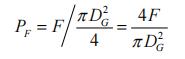
(2) Equivalent stress PF generated by axial force F
The axial force F is equivalent to the internal pressure in the DG range, namely:
(3) Equivalent stress PM produced by external moment M
The maximum stress caused by the external moment M acting on the gasket is:
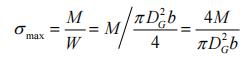
Among , b is the width of the gasket.
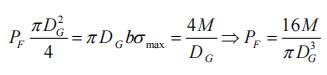
The axial force caused by the stress acting on the gasket area is equivalent to the axial force caused by the internal pressure, namely:
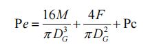
Combining the above three items, the calculation formula for the equivalent calculation pressure is:
3. ASME's regulations for the selection of standard flanges
1. Introduction
The design conditions of the complete equipment usually include the pipeline load, which is generally provided by the pipeline professional. In the design process, the load is usually used to check the partial stress between the connecting pipe and shell so as to prevent the failure of the connecting part of the connecting pipe and shell. However, there are some doubts about whether the load should also be applied to the calculation of flanges:
(1) Specifications of flanges (standard flanges) are usually given by pipelines, and may have passed the piping design to meet the pipeline connection.
(2) The standard flange selected for the pipeline has a certain ability to withstand external loads.
(3) The pipe load provided may be a conservative value estimated in the previous period. If the flange is designed under this condition, the required flange will be much larger than the matched flange.
At the same time, considering the failure of the flange, which is usually the leakage. To ensure that the flange does not leak, it is necessary to ensure that there is a certain pressure on the gasket (mandatory sealing flanges). Therefore, the design of bolts and flanges must take into account the packing force on the gasket being reduced, manly the influence of internal pressure to offset part of the bolt's tightening force and external load to offset part of the bolt's tightening force and make the bolt force no longer balanced. Therefore, the calculation of flange under internal pressure and external load is also a topic that needs to be discussed.
2. Current calculation methods
2.1 An introduction to the current calculation method
At present, China's main requirements for flanges withstanding external loads are as follows:
(1) HG/T 20582-2011 pointed out that in addition to bearing internal pressure, flanges also bear great axial forces and external moments such as the weight of vertical equipment, wind load, force and moment caused by seismic loads or pipes. At this time, only design or select flanges based on internal pressure is unsafe, and the equivalent design pressure should be calculated according to the following formula:
(2) NB/T 47041-2014 stipulates that when each section of the tower shell is connected by flanges, the impact of internal pressure, axial force and external moment should also be considered for flanges, and the equivalent design pressure is calculated by the following formula:
The expressions of the above two are almost the same, and the equivalent design pressure is introduced for the external loads. The calculation method is the same. At present, the calculation software SW6 which is widely used in the design of pressure vessels also adopts the above-mentioned processing method for the external load of the flange.
2.2 Applicable scopes of equivalent pressure calculation
HG 20582-2011 "Instructions of Compilation " clearly states the following two aspects:
(1) This method is mainly recommended for the selection of standard flanges.
(2) This method is limited to flanges with flat gasket seals, and is not used for flanges with other seals.
Therefore, the equivalent pressure calculation is not applicable to all sealing surfaces, and it may not be completely suitable for design calculations of flanges. The flange sealing surface should be paid attention to for the formula in NB/T47040-2014, but most equipment flanges mainly have flat gasket seals.
2.3 The formula of equivalent design pressure formula
The equivalent design pressure calculation formula of the flange consists of three parts:
(1) Design internal pressure P
(2) Equivalent stress PF generated by axial force F
The axial force F is equivalent to the internal pressure in the DG range, namely:
(3) Equivalent stress PM produced by external moment M
The maximum stress caused by the external moment M acting on the gasket is:
Among
, b is the width of the gasket.The axial force caused by the stress acting on the gasket area is equivalent to the axial force caused by the internal pressure, namely:
Combining the above three items, the calculation formula for the equivalent calculation pressure is:
3. ASME's regulations for the selection of standard flanges
Article 4.16.12 in the new version of ASME VIW-DIV2 2019 stipulates that the selection of standard flanges for bearing force and external torque should meet the requirements of the following formula:
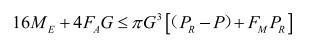
Among them, PR is the maximum allowable working pressure under the corresponding materials and temperatures of the standard flange, and FM is the torque coefficient, which is obtained according to table 4. 16.12. Generally, 0.3 to 1.2 is used for pipe flanges conforming to ASME B16.5. After deforming the above formula, we can get the following formula:
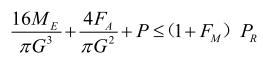
The left side of this inequality is consistent with the calculation formula of equivalent design pressure in the previous section, and the right side is equivalent to magnifying the maximum allowable working pressure of the standard flange by 0.3 to 1.2 times.
It can be seen that this requirement undoubtedly improves the ability of the standard flange to withstand the external load, which is more economical than the calculation method in the previous section.
4. A comparison of the calculation of the flange
In the design of equipment, standard flanges can often be selected instead of flange calculations. In the actual design, the standard flange is not applicable and the flange size needs to be determined by calculation. At this time, the calibration calculation of the flange needs to be carried out according to the standard.
The calculation of the flange in GB150 does not include the situation that the flange bears external force and external moment. For the flange in this situation, the flange equivalent design pressure can be calculated first, and then calculate the flange's strength.
The flange's calculation in the ASME standard is similar to that of GB150, and at the same time, it uses the classic Waters flange calculation. The difference is that the calculation formula given in ASME VI-2 2019 includes the calculation method of flange bolts and flange torque in the case of external force and external torque. The minimum bolt area required is as follows:
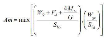
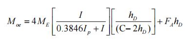
After considering the external force and external torque, the flange torque is calculated as follows:
Through actual calculations, it is found that from the calculation of the flange, the selection of the flange to the strength calculation of the flange, ASMEVIu-22019 is more economical and has a wider scope of application.
5. Conclusion
After the above comparison and analysis, we found that ASMEVI-22019 is more economical for the selection of standard flanges to non-standard flanges. For future flange design, it has the following reference significance:
(1) For flanges with flat gaskets, it is necessary to calculate the flange equivalent calculation pressure according to the requirements of HG/T20582, and then select the appropriate flange; for flanges without flat gaskets, determine the maximum allowable working pressure of the flange when there is an external load (equivalent to increasing the maximum allowable working pressure by FM times) according to 4.16.12 of ASME VI-2 2019.
(2) For the design of non-standard flanges without flat gaskets, the influence of external loads on bolts and flange moments can be dealt with based on ASME VIm-2 2019. Use this to calculate the appropriate bolt area and get a reasonable size for the flange.
Among them, PR is the maximum allowable working pressure under the corresponding materials and temperatures of the standard flange, and FM is the torque coefficient, which is obtained according to table 4. 16.12. Generally, 0.3 to 1.2 is used for pipe flanges conforming to ASME B16.5. After deforming the above formula, we can get the following formula:
The left side of this inequality is consistent with the calculation formula of equivalent design pressure in the previous section, and the right side is equivalent to magnifying the maximum allowable working pressure of the standard flange by 0.3 to 1.2 times.
It can be seen that this requirement undoubtedly improves the ability of the standard flange to withstand the external load, which is more economical than the calculation method in the previous section.
4. A comparison of the calculation of the flange
In the design of equipment, standard flanges can often be selected instead of flange calculations. In the actual design, the standard flange is not applicable and the flange size needs to be determined by calculation. At this time, the calibration calculation of the flange needs to be carried out according to the standard.
The calculation of the flange in GB150 does not include the situation that the flange bears external force and external moment. For the flange in this situation, the flange equivalent design pressure can be calculated first, and then calculate the flange's strength.
The flange's calculation in the ASME standard is similar to that of GB150, and at the same time, it uses the classic Waters flange calculation. The difference is that the calculation formula given in ASME VI-2 2019 includes the calculation method of flange bolts and flange torque in the case of external force and external torque. The minimum bolt area required is as follows:
After considering the external force and external torque, the flange torque is calculated as follows:
Through actual calculations, it is found that from the calculation of the flange, the selection of the flange to the strength calculation of the flange, ASMEVIu-22019 is more economical and has a wider scope of application.
5. Conclusion
After the above comparison and analysis, we found that ASMEVI-22019 is more economical for the selection of standard flanges to non-standard flanges. For future flange design, it has the following reference significance:
(1) For flanges with flat gaskets, it is necessary to calculate the flange equivalent calculation pressure according to the requirements of HG/T20582, and then select the appropriate flange; for flanges without flat gaskets, determine the maximum allowable working pressure of the flange when there is an external load (equivalent to increasing the maximum allowable working pressure by FM times) according to 4.16.12 of ASME VI-2 2019.
(2) For the design of non-standard flanges without flat gaskets, the influence of external loads on bolts and flange moments can be dealt with based on ASME VIm-2 2019. Use this to calculate the appropriate bolt area and get a reasonable size for the flange.

Related News
- Failure Analysis of Cracking in a 16MnⅢ Weld Neck Flange
- ANSYS Analysis for Anchor Flange Structural Optimization
- Flange Leakage in Hydrogen-Cooled Pipeline Systems of Thermal Power Plants
- Flange Sealing Technology and Installation Method for Hydrogenation Units
- Multi-Directional Die Forging Process for Horizontal Valve Bodies with Dual Flanges
- Structural Performance Analysis of Zirconium Pressure Vessel Lap Joint Flanges
- Low-Temperature Flange Sealing Solutions for Cryogenic Chemical Pipelines
- Innovative Technology for Automatic Alignment in Underwater Flange Assembly
- Stamped Steel Slip-On Flanges
- Design and Finite Element Analysis of Anchor Flanges for Oil & Gas Pipelines