Controlling Deformation of Slip-on Flanges with Large Diameters
A batch of flanges for ethylene engineering are manufactured in a factory recently. There are some problems in the manufacturing process. One of the prominent problems is how to control the deformation of slip-on flanges with large diameters during assembly.
This batch of slip-on flanges has the following characteristics
1. Most of the nominal diameters are between 800 to 2000mm. The operating pressure is low pressure or normal pressure. The main flange and the connecting flange are slip-on flanges with small thickness, and the wall thickness of the cylinder, head and pipe box is within 4 to 12mm.
2. The slip-on flange is required to have thermal strength and corrosion resistance, mainly acetic acid corrosion, oxidation resistance and low-temperature resistance, so heat exchange tubes and tube sheets are mostly made from austenitic stainless steel and ultra-low carbon alloy steel, such as 1Cr18Ni9Ti, 0Cr17Ni13Mo2Ti, 00Cr20Ni17Mo5, 1Cr18Ni12Mo2Ti, etc.
3. Flanges are generally made from carbon steel or low-grade steel, and some are welded with stainless steel strips; some are directly welded with the tube sheet and the cylinder. See Figures 2 and 5. The flange is seriously deformed after assembly and welding due to these characteristics, and its deformation includes angular deformation, unevenness and ovality, and some deformations will exceed people's estimates, making the sealing fail. The flange bolts cannot enter the hole, or the deformation exceeds the machining allowance, resulting in the inability to implement post-weld processing. For this reason, it is very important to formulate a reasonable and reliable manufacturing process when the structural form has been determined.
Generally speaking, the flange’s sealing surface should be processed after welding. When the equipment capacity allows, it is better to process the parts as a whole. If it cannot be processed as a whole, a short joint of the cylinder should be provided. The short joint is welded to the flange first, and then welded to form shells and tube boxes. No matter which method is used, it is very important to control the deformation. Of course, when the structure or other conditions make it impossible to arrange post-weld processing, its importance is even more obvious. The following are some typical structures, and the manufacturing, installation and welding procedures adopted are briefly introduced.
The structure
The welding seams are dense. The welding seam has big sizes; the filler metal is much, and the welding deformation is great. Manufacturing process characteristics are as follows:
1. Installation of tube bundles, including penetration of pipes, assembly positioning, and spot welding pipe ends
2. Put the tube bundle into the cylinder. Spot weld the tube sheet, and install the positioning spot welding flange; install the process flange. The process flange is a rigid slip-on flange ring, which is fastened with the product flange with bolts.
3. Weld the welding seam a for 1 to 3 times. Use the electrode with a thickness of 3.2mm for the first time, and 4mm for the second and third times.
4. Weld the pipe end. Firstly, positioning welding should be performed. Second, the two ends are divided, and the welding is symmetrical from the center to the outside.
5. Complete the welding of welding seam a.
6. Weld the welding seam. After one layer of welding, cool to less than 60°C and then weld the second layer, which is good for releasing the stress on the welding seam.
7. Perform welding seam C.
8. The sealing surface is processed integrally.
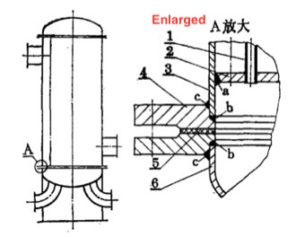
Figure 1 The structure of a large dense welding seam
1. Heat exchange tubes 2. Tube sheets 3. Cylinders 4. Flanges 5. Gaskets 6. Heads
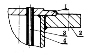
Figure 2 The welding structure of short joints of cylinder bodies
1. Tube sheets 2. Flanges 3. Heat exchange tubes 4. Simplified short joints
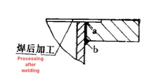
Figure 3 Processing positions of concave tube sheets
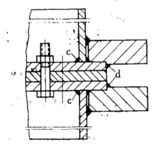
Figure 4 The welding of the intermediate clip process plate
For the welding of flanges and heads, refer to the above b and c welding seams, and process the sealing surface after welding. It is also stipulated in welding that the diameter of the electrode is 3.2mm or 4mm. It is strictly forbidden to use large-diameter electrodes. It is strictly forbidden to swing laterally. The welding should be performed at a slow speed. Generally, the swing width does not exceed 1.5 times the diameter of the electrode. Use short arc length and rapid welding methods. This provision also applies to the structures shown in Figures 2 and 3.
The structure of Figure 2
The two-stage cylinder short joint is adopted, and the manufacturing points are as follows: ① The two tube sheets are overlapped and then drilled. ② The short joint of the cylinder body is assembled with the flange, and welding should be performed in the order of a and b. The concave surface of the tube sheet is processed after welding, as shown in Figure 3. ③ Perform spot welding for the tube sheet and the flange, and then put the same two parts back to back; tighten the tube sheet with enough bolts. Put a process plate with appropriate thickness in the middle, so that the welding seam d can be easily welded. As shown in Figure 4, perform welding in the order of c and d. ④ Disassemble and process the sealing surface of the tube sheet. ⑤ Mark and drill flange bolt holes. ⑥ The two circumferential seams of the above short joint parts of the cylinder body and the simplified assembly welding shall be welded after the tube bundle is pierced, and the lining ring structure shall be adopted. Before the circumferential seam is welded, the heat exchange tube can only be welded on the tube sheet at one end, and the other end will be spot welded after the circumferential seam is welded; perform welding.
The structure of Figure 5
This structure is often used for the main body flange or the connecting flange. When it is used in the main body flange, the nominal diameter is very large, and the flange thickness is small, resulting in great welding deformation, which is difficult to control.
Matters that should be paid attention to in manufacturing are: ① The lining ring is welded with the flange and leveled after welding. ② Assemble and spot weld the short joint of the cylinder body head or connecting pipe. Perform welding in sequences of a and b. After welding seam a is welded once, then welding seam b is also welded again; repeat this process. For large-diameter flanges, it is best to weld one welding symmetrically by two welders at the same time. ③ Process the sealing surface of the lining ring.
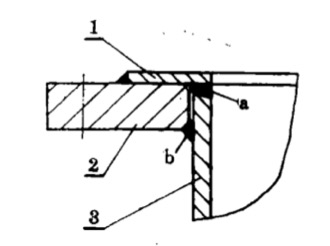
1. Lining strips 2. Flanges 3. Cylinder shot joints, heads or connecting pipes
Figure 5 Welding of main flanges or flanges connecting pipes
The practice has proved that as long as a reasonable and reliable manufacturing process is formulated, the process should be strictly carried out, and the normal process sequence can be guaranteed; the deformation can be controlled within a small range, so high-quality flanges can be guaranteed.
This batch of slip-on flanges has the following characteristics
1. Most of the nominal diameters are between 800 to 2000mm. The operating pressure is low pressure or normal pressure. The main flange and the connecting flange are slip-on flanges with small thickness, and the wall thickness of the cylinder, head and pipe box is within 4 to 12mm.
2. The slip-on flange is required to have thermal strength and corrosion resistance, mainly acetic acid corrosion, oxidation resistance and low-temperature resistance, so heat exchange tubes and tube sheets are mostly made from austenitic stainless steel and ultra-low carbon alloy steel, such as 1Cr18Ni9Ti, 0Cr17Ni13Mo2Ti, 00Cr20Ni17Mo5, 1Cr18Ni12Mo2Ti, etc.
3. Flanges are generally made from carbon steel or low-grade steel, and some are welded with stainless steel strips; some are directly welded with the tube sheet and the cylinder. See Figures 2 and 5. The flange is seriously deformed after assembly and welding due to these characteristics, and its deformation includes angular deformation, unevenness and ovality, and some deformations will exceed people's estimates, making the sealing fail. The flange bolts cannot enter the hole, or the deformation exceeds the machining allowance, resulting in the inability to implement post-weld processing. For this reason, it is very important to formulate a reasonable and reliable manufacturing process when the structural form has been determined.
Generally speaking, the flange’s sealing surface should be processed after welding. When the equipment capacity allows, it is better to process the parts as a whole. If it cannot be processed as a whole, a short joint of the cylinder should be provided. The short joint is welded to the flange first, and then welded to form shells and tube boxes. No matter which method is used, it is very important to control the deformation. Of course, when the structure or other conditions make it impossible to arrange post-weld processing, its importance is even more obvious. The following are some typical structures, and the manufacturing, installation and welding procedures adopted are briefly introduced.
The structure
The welding seams are dense. The welding seam has big sizes; the filler metal is much, and the welding deformation is great. Manufacturing process characteristics are as follows:
1. Installation of tube bundles, including penetration of pipes, assembly positioning, and spot welding pipe ends
2. Put the tube bundle into the cylinder. Spot weld the tube sheet, and install the positioning spot welding flange; install the process flange. The process flange is a rigid slip-on flange ring, which is fastened with the product flange with bolts.
3. Weld the welding seam a for 1 to 3 times. Use the electrode with a thickness of 3.2mm for the first time, and 4mm for the second and third times.
4. Weld the pipe end. Firstly, positioning welding should be performed. Second, the two ends are divided, and the welding is symmetrical from the center to the outside.
5. Complete the welding of welding seam a.
6. Weld the welding seam. After one layer of welding, cool to less than 60°C and then weld the second layer, which is good for releasing the stress on the welding seam.
7. Perform welding seam C.
8. The sealing surface is processed integrally.
Figure 1 The structure of a large dense welding seam
1. Heat exchange tubes 2. Tube sheets 3. Cylinders 4. Flanges 5. Gaskets 6. Heads
Figure 2 The welding structure of short joints of cylinder bodies
1. Tube sheets 2. Flanges 3. Heat exchange tubes 4. Simplified short joints
Figure 3 Processing positions of concave tube sheets
Figure 4 The welding of the intermediate clip process plate
For the welding of flanges and heads, refer to the above b and c welding seams, and process the sealing surface after welding. It is also stipulated in welding that the diameter of the electrode is 3.2mm or 4mm. It is strictly forbidden to use large-diameter electrodes. It is strictly forbidden to swing laterally. The welding should be performed at a slow speed. Generally, the swing width does not exceed 1.5 times the diameter of the electrode. Use short arc length and rapid welding methods. This provision also applies to the structures shown in Figures 2 and 3.
The structure of Figure 2
The two-stage cylinder short joint is adopted, and the manufacturing points are as follows: ① The two tube sheets are overlapped and then drilled. ② The short joint of the cylinder body is assembled with the flange, and welding should be performed in the order of a and b. The concave surface of the tube sheet is processed after welding, as shown in Figure 3. ③ Perform spot welding for the tube sheet and the flange, and then put the same two parts back to back; tighten the tube sheet with enough bolts. Put a process plate with appropriate thickness in the middle, so that the welding seam d can be easily welded. As shown in Figure 4, perform welding in the order of c and d. ④ Disassemble and process the sealing surface of the tube sheet. ⑤ Mark and drill flange bolt holes. ⑥ The two circumferential seams of the above short joint parts of the cylinder body and the simplified assembly welding shall be welded after the tube bundle is pierced, and the lining ring structure shall be adopted. Before the circumferential seam is welded, the heat exchange tube can only be welded on the tube sheet at one end, and the other end will be spot welded after the circumferential seam is welded; perform welding.
The structure of Figure 5
This structure is often used for the main body flange or the connecting flange. When it is used in the main body flange, the nominal diameter is very large, and the flange thickness is small, resulting in great welding deformation, which is difficult to control.
Matters that should be paid attention to in manufacturing are: ① The lining ring is welded with the flange and leveled after welding. ② Assemble and spot weld the short joint of the cylinder body head or connecting pipe. Perform welding in sequences of a and b. After welding seam a is welded once, then welding seam b is also welded again; repeat this process. For large-diameter flanges, it is best to weld one welding symmetrically by two welders at the same time. ③ Process the sealing surface of the lining ring.
1. Lining strips 2. Flanges 3. Cylinder shot joints, heads or connecting pipes
Figure 5 Welding of main flanges or flanges connecting pipes
The practice has proved that as long as a reasonable and reliable manufacturing process is formulated, the process should be strictly carried out, and the normal process sequence can be guaranteed; the deformation can be controlled within a small range, so high-quality flanges can be guaranteed.

Related News
- Failure Analysis of Cracking in a 16MnⅢ Weld Neck Flange
- ANSYS Analysis for Anchor Flange Structural Optimization
- Flange Leakage in Hydrogen-Cooled Pipeline Systems of Thermal Power Plants
- Flange Sealing Technology and Installation Method for Hydrogenation Units
- Multi-Directional Die Forging Process for Horizontal Valve Bodies with Dual Flanges
- Structural Performance Analysis of Zirconium Pressure Vessel Lap Joint Flanges
- Low-Temperature Flange Sealing Solutions for Cryogenic Chemical Pipelines
- Innovative Technology for Automatic Alignment in Underwater Flange Assembly
- Stamped Steel Slip-On Flanges
- Design and Finite Element Analysis of Anchor Flanges for Oil & Gas Pipelines