
Flanges for Faster Installation and Maintenance
Unlike permanent welded joints, flanged connections can be assembled and disassembled using bolts and appropriate gaskets. This characteristic is particularly valuable in industrial facilities where equipment must be periodically inspected, cleaned, repaired, or replaced. Refineries, chemical plants, power stations, water-treatment facilities, shipyards, steel mills, and offshore installations all rely extensively on flanged connections.
Flange performance, however, depends on much more than the flange itself. The flange type, material, pressure class, facing, gasket, bolt system, pipe alignment, tightening procedure, operating temperature, and pressure all influence connection reliability. Modern flange engineering is therefore increasingly focused on the complete joint rather than treating the flange as an isolated component.
One of the most important advantages of a flange is its detachable construction. A welded pipe joint creates a permanent connection that normally requires cutting, preparation, welding, inspection, and potentially post-weld treatment when the system needs to be modified or repaired. A flanged joint, by contrast, can be separated by removing the fasteners.
This feature can significantly simplify the installation of valves, pumps, strainers, expansion joints, filters, instrumentation assemblies, and other components that may eventually require replacement. When properly engineered, the flange provides a standardized interface between components from different parts of a piping system.
The practical installation sequence is generally straightforward:
- Align the mating flanges.
- Position the correct gasket.
- Insert and hand-tighten the bolts.
- Apply the specified tightening sequence.
- Tighten to the required torque or tension.
- Verify alignment and connection condition.
- Perform the required pressure or leak test.
Although the procedure appears simple, professional flange assembly requires careful control of gasket placement, bolt tightening, flange alignment, and surface condition.
Industrial equipment is rarely static throughout its entire lifecycle. Pumps, valves, heat exchangers, instruments, filters, and other components may require replacement because of wear, corrosion, process upgrades, or capacity changes.
A flanged connection provides a practical interface for such replacement work. Instead of modifying the surrounding pipework through cutting and welding, maintenance personnel can isolate the system, depressurize it, remove the bolts, replace the component or gasket, and reassemble the connection.
This is especially valuable in facilities where production downtime is expensive. The ability to plan maintenance around standardized flange connections can reduce the amount of hot work and shorten the duration of certain maintenance activities.
A flange connection performs two fundamental mechanical functions: load transfer and pressure sealing.
The bolts generate a compressive force that clamps the two flange faces together. The gasket positioned between the faces is compressed and deformed, filling surface irregularities and creating a barrier against fluid leakage.
During operation, the internal pressure attempts to separate the flanges. The joint must therefore maintain sufficient bolt preload and gasket compression to prevent leakage while also avoiding excessive stress on the flange, bolts, gasket, or connected piping.
The simplified load path can be understood as:
Internal pressure → separating force → flange/bolt reaction → gasket compression → sealed connection
The actual engineering analysis is more complicated because thermal expansion, external piping loads, bending moments, vibration, gasket relaxation, bolt relaxation, and material deformation can alter the load distribution.
A common misconception is that the flange itself provides the primary seal. In most conventional bolted flange assemblies, the gasket is a critical sealing element.
Different services may require different gasket constructions, including:
- Spiral-wound gaskets
- Ring-type joint gaskets
- Compressed fiber gaskets
- PTFE gaskets
- Graphite gaskets
- Metal-jacketed gaskets
- Elastomeric gaskets
The gasket must be compatible with the process medium, pressure, temperature, flange facing, and expected operating conditions.
Consequently, selecting a flange without simultaneously specifying an appropriate gasket can result in an incomplete engineering solution.
Industrial flanges can be classified according to connection method, construction, facing, pressure rating, and application. Several common types are used throughout the piping industry.
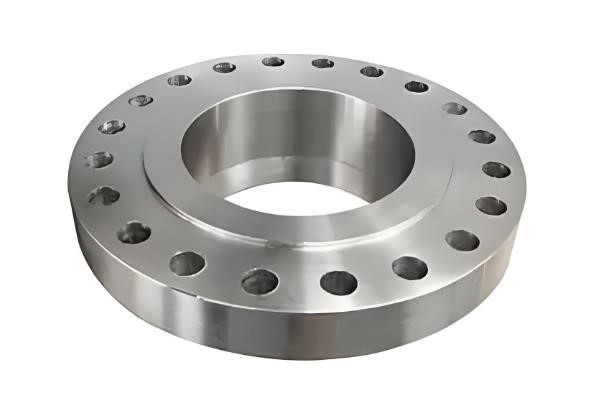
Slip-on flanges are designed so that the pipe passes through the flange before welding. They are relatively easy to align and install, which makes them attractive for many general-purpose piping systems.
Because the pipe is inserted into the flange, fabrication involves welding around the pipe connection. Slip-on flanges are commonly found in low- and moderate-pressure services where installation simplicity and cost are important.
However, they may not provide the same fatigue performance as properly designed butt-welded connections under severe cyclic conditions. Therefore, application requirements should determine whether slip-on or weld-neck construction is appropriate.
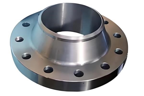
Weld-neck flanges are connected to the pipe using a butt weld. Their long tapered hub provides a gradual transition from the flange thickness to the pipe wall, helping distribute mechanical stresses.
They are widely used for high-pressure, high-temperature, and severe-service applications. The butt-weld configuration can also provide favorable fatigue performance when correctly designed and fabricated.
Weld-neck flanges generally require more fabrication effort than slip-on flanges, but their mechanical performance can justify the additional cost in demanding services.
Socket weld flanges have a socket into which the pipe is inserted before welding. They are commonly used for smaller-diameter piping where high-pressure service requires a compact flange connection.
The configuration provides convenient pipe alignment and is frequently used in instrumentation, utility, and process piping applications.
However, the design and fabrication procedure must follow the applicable piping code and project specification, particularly concerning weld geometry and dimensional requirements.
Threaded flanges connect to pipes through internal threads and therefore do not require welding. This can be useful where welding is undesirable or impractical.
Threaded flanges are generally selected for appropriate low- or moderate-pressure services and applications where the piping material and thread design are compatible.
They are not automatically suitable for high-temperature or severe cyclic applications because thread connections can introduce stress concentrations and may create additional leakage considerations.
Lap joint flanges are used with stub ends and are particularly useful when piping requires frequent disassembly or when expensive corrosion-resistant pipe materials are involved.
The flange itself does not need to be in direct contact with the process fluid in the same way as some other flange arrangements. This can allow a relatively economical flange material to be combined with a corrosion-resistant stub end.
Lap joint construction also provides some rotational freedom during assembly, which can simplify bolt-hole alignment.
Blind flanges have no central bore and are used to close the end of a pipe, nozzle, or vessel connection. They are important for system isolation, pressure testing, future expansion, and maintenance.
A blind flange must be designed to withstand the pressure-induced loads generated across its closed face. As pressure increases, the structural demands on the blind flange become increasingly important.
Blind flanges are commonly installed on vessel nozzles, pipeline branches, pump connections, and unused piping ends.
Raised-face flanges are widely used in industrial piping. The raised sealing surface concentrates gasket compression over a defined area and can facilitate reliable sealing when the flange and gasket are correctly matched.
Raised-face configurations are common in chemical, petrochemical, power-generation, and general industrial piping systems.
Flat-face flanges have a sealing surface that is approximately coplanar with the flange face. They may be used with certain equipment and piping configurations where excessive localized stress must be avoided.
Flat-face configurations require careful gasket and bolting selection because the joint behavior differs from that of raised-face arrangements.
Ring-type joint, or RTJ, flanges use a machined metallic ring groove. A metallic ring gasket is installed into the groove and compressed during bolting.
RTJ connections are commonly associated with high-pressure and high-temperature applications, particularly in oil and gas service. The precise machining of the groove and ring gasket is critical because sealing depends strongly on the geometry and surface condition of the joint.
Carbon steel is widely used because of its combination of strength, availability, machinability, and cost. Common carbon-steel flange materials include ASTM A105 forgings for many piping applications.
Carbon steel flanges are frequently used in water, steam, oil, gas, and general industrial systems. However, corrosion protection may be necessary depending on the environment.
Stainless steel flanges are selected where corrosion resistance, cleanliness, or elevated-temperature performance is required. Common materials include 304/304L and 316/316L stainless steels.
316/316L is particularly useful where improved resistance to chloride-containing environments is needed compared with standard 304 stainless steel, although material suitability still depends on the actual process conditions.
High-temperature, low-temperature, highly corrosive, or sour-service applications may require alloy steels, nickel alloys, duplex stainless steels, super duplex stainless steels, or other specialized materials.
Material selection should consider both flange performance and compatibility with the pipe and process fluid. Dissimilar-metal combinations may also require attention to galvanic corrosion, thermal expansion differences, and fabrication requirements.
One of the major reasons flanges improve installation efficiency is standardization. Dimensions such as outside diameter, bolt-hole pattern, bore, thickness, and facing configuration are defined by applicable standards.
ASME B16.5 covers pipe flanges and flanged fittings in specified sizes and pressure classes, while ASME B16.47 covers larger-diameter steel flanges. ASME B16.48 addresses line blanks, including spectacle blinds and spacers used in piping systems.
Standardization allows engineers and procurement teams to specify compatible components without developing completely customized connection dimensions for every project.
Common ASME pressure classes include:
- Class 150
- Class 300
- Class 400
- Class 600
- Class 900
- Class 1500
- Class 2500
The pressure-temperature rating must always be evaluated using the applicable standard and flange material. A flange marked “Class 600” should not be interpreted as having one universal maximum pressure regardless of temperature and material.
As temperature increases, allowable pressure may decrease depending on the material and applicable standard. This is particularly important for steam and high-temperature process piping.
Engineers should therefore evaluate the actual pressure-temperature combination rather than selecting a flange based only on nominal pressure.
A complete specification may include:
Size + flange type + material + pressure class + facing + applicable standard
For example, a project specification might identify a flange using dimensions and material requirements based on ASME and ASTM standards.
The flange and gasket cannot function properly without suitable bolting. Bolts or studs provide the clamping force necessary to compress the gasket and maintain the joint during operation.
Bolt preload should be sufficient to:
- Compress the gasket adequately
- Resist pressure-induced separation
- Accommodate external loads
- Maintain sealing during thermal cycling
- Compensate for certain relaxation effects
However, excessive preload can also cause problems, including flange distortion, gasket damage, bolt yielding, or excessive local stresses.
Therefore, tightening should be based on an engineered procedure rather than simply “tighten as much as possible.”
For many conventional circular flange assemblies, bolts are tightened in a controlled sequence, commonly using a cross or star pattern. The objective is to distribute gasket compression progressively and minimize uneven loading.
A typical sequence involves:
- Initial hand tightening.
- Low-percentage torque pass.
- Intermediate torque pass.
- Final torque pass.
- Verification pass if required.
The exact procedure should follow the gasket manufacturer's recommendations, project specifications, applicable codes, and bolting engineering requirements.
For critical connections, hydraulic tensioning or other controlled bolting technologies may be used to achieve more consistent preload.
Even a correctly selected flange can leak if the piping system is poorly aligned. Excessive angular or parallel misalignment can place additional loads on the flange and gasket.
Forcing two misaligned flanges together with bolts may temporarily create a connection, but it can introduce undesirable stresses into the piping system and connected equipment.
Installation teams should therefore verify:
- Flange parallelism
- Pipe alignment
- Bolt-hole alignment
- Gasket centering
- Pipe support condition
- Equipment nozzle alignment
- Absence of excessive external loads
The flange should not be used as a tool for pulling significantly misaligned piping into position.
Gaskets should be handled carefully and kept clean. Damaged, contaminated, incorrectly sized, or previously compressed gaskets can compromise sealing performance.
For many gasket types, reuse is not recommended because the material may have undergone permanent deformation during the first installation.
The correct gasket should always be selected for the specific flange facing and operating conditions.
One of the most valuable characteristics of flanged connections is accessibility. When the system is safely isolated and depressurized, technicians can remove the connection and inspect the flange face, gasket, bolts, pipe end, and nearby components.
This facilitates identification of:
- Corrosion
- Erosion
- Gasket deterioration
- Flange-face damage
- Bolt corrosion
- Thread damage
- Misalignment
- Mechanical deformation
Such inspections can provide valuable information for maintenance planning.
A valve connected by flanges can usually be removed without cutting the adjacent pipe. This is particularly advantageous for large valves and equipment that may have long service lives but require periodic maintenance.
For example, a failed butterfly valve in a water-treatment system can potentially be isolated, unbolted, replaced, and recommissioned without major modification to the pipeline.
This is one reason standardized flanged interfaces are common in equipment-intensive industrial facilities.
High-temperature and high-pressure applications impose additional demands on flange joints. Thermal expansion can cause changes in bolt preload, gasket stress, pipe loads, and equipment alignment.
During startup and shutdown, components may experience repeated thermal cycling. These cycles can create fatigue stresses and influence gasket performance.
For demanding services, engineers may need to evaluate:
- Flange rigidity
- Bolt material
- Gasket behavior
- Thermal expansion
- External piping loads
- Pressure-induced separation
- Fatigue
- Creep at elevated temperature
- Joint relaxation
The flange should therefore be analyzed as part of the piping system rather than as an isolated component.
The internal flange surfaces and gasket interface can be exposed to process fluids, particularly where the flange configuration places metal directly in the flow path.
Corrosive services may require stainless steel, alloy materials, corrosion-resistant coatings, liners, or other protective measures.
Chemical compatibility must be evaluated for the flange, gasket, pipe, bolts, and other wetted components.
Outdoor flange assemblies are exposed to rain, humidity, salt spray, industrial pollutants, and temperature changes. Bolt threads and crevices around the flange can become corrosion sites.
Protective coatings, suitable materials, proper drainage, and periodic inspection can help extend service life.
In marine and offshore applications, corrosion protection becomes particularly important because chloride-rich environments can accelerate degradation of susceptible materials.
Flanges are also frequently used to connect expansion joints, flexible connectors, rubber joints, and other components that accommodate thermal or mechanical movement.
This arrangement can simplify installation because the flexible component can be bolted between standardized pipe flanges.
However, the piping system must be designed so that the expansion joint is not subjected to loads beyond its intended function. Improper pipe supports or excessive pressure thrust can cause deformation or failure.
The flange connection therefore forms part of a larger mechanical system involving anchors, guides, supports, and flexible elements.
Advanced composite materials such as carbon-fiber-reinforced polymers can offer attractive combinations of low weight, strength, and corrosion resistance in specialized applications.
Weight reduction can be particularly valuable in aerospace, marine, offshore, and certain high-performance transportation systems. However, composite flange design requires careful consideration of anisotropic mechanical properties, temperature resistance, bolting loads, creep, and long-term environmental exposure.
For mainstream industrial pressure piping, metallic flanges remain dominant because of established standards, manufacturing infrastructure, inspection practices, and long-term service experience.
Surface-engineering technologies can improve resistance to wear and corrosion. Depending on the application, coatings may reduce surface degradation, improve hardness, or provide a barrier against corrosive environments.
The selection of a coating must consider adhesion, substrate compatibility, operating temperature, chemical exposure, coating thickness, and potential damage during installation.
A coating should therefore be considered as part of an engineered corrosion-control strategy rather than simply as an additional surface treatment.
Additive manufacturing, commonly known as 3D printing, provides new possibilities for producing complex geometries and customized components. It can be particularly useful for prototypes, low-volume specialized components, and geometries that are difficult to manufacture through conventional processes.
However, industrial pressure-containing flange applications require rigorous control of material properties, dimensional accuracy, defects, surface condition, qualification, inspection, and applicable code compliance.
Therefore, additive manufacturing should currently be viewed as a specialized manufacturing route rather than a universal replacement for forged or cast flange production.
The future of flange management is increasingly connected with digital inspection and asset-management systems. Industrial facilities can use digital records to track flange locations, materials, gasket specifications, bolting procedures, inspection history, and leakage events.
A digital flange-management system may contain:
- Flange identification number
- Piping line number
- Size and pressure class
- Material
- Facing type
- Gasket specification
- Bolt specification
- Installation date
- Tightening method
- Inspection history
- Leakage history
- Maintenance records
This information can make maintenance more systematic and reduce the risk of installing an incorrect gasket or bolt set during repair.
For large facilities containing thousands of flange connections, digital documentation can become an important part of mechanical-integrity management.
Flanged and welded connections each have appropriate applications.
| Factor | Flanged connection | Welded connection |
|---|---|---|
| Disassembly | Easy relative to welded joints | Difficult |
| Equipment replacement | Convenient | Usually requires cutting and rewelding |
| Installation | Relatively straightforward | Requires qualified welding |
| Maintenance access | Excellent | Limited |
| Leakage potential | Requires gasket integrity | No conventional gasket |
| Hot work | Generally reduced | Required for welding |
| Weight | Higher | Lower |
| Space | Requires bolt clearance | More compact |
| Inspection | Flange/gasket/bolting accessible | Weld NDE required |
| High-temperature service | Widely used with suitable design | Widely used |
| Large equipment connections | Highly practical | Application dependent |
The comparison demonstrates that flange connections are particularly valuable where maintenance accessibility and equipment replacement are important. Welded connections may be preferable where permanent, compact, lightweight, or highly leak-tight construction is prioritized.
Many industrial piping systems therefore use both technologies rather than choosing exclusively between them.
A practical flange-selection procedure can be organized into several stages.
Determine:
- Fluid composition
- Normal pressure
- Design pressure
- Normal temperature
- Design temperature
- Corrosivity
- Toxicity
- Flammability
- Flow characteristics
These parameters establish the basic material and pressure requirements.
Confirm pipe outside diameter, wall thickness, nominal pipe size, equipment nozzle dimensions, bore requirements, and bolt-hole pattern.
Dimensional compatibility is essential because a flange cannot compensate for fundamentally incompatible interfaces.
Choose among weld neck, slip-on, socket weld, threaded, lap joint, blind, or other configurations according to pressure, temperature, installation, maintenance, and mechanical requirements.
The flange material must be compatible with the process and mechanical conditions. Facing selection must correspond to the gasket and mating flange.
The flange, gasket, and bolts should be treated as a single engineered joint. Gasket material, thickness, bolt grade, preload, and tightening procedure must be mutually compatible.
Confirm dimensional, material, pressure-rating, testing, marking, and inspection requirements against the applicable project standards and codes.
Despite advances in welded connections, composite materials, additive manufacturing, and other joining technologies, flanges remain indispensable because their fundamental engineering advantages are difficult to replace.
They provide:
- Standardized interfaces
- Mechanical strength
- Reliable sealing
- Easy disassembly
- Equipment interchangeability
- Maintenance accessibility
- Flexible system configuration
- Compatibility with valves and process equipment
Their importance is especially clear in facilities where equipment must be maintained over decades. A refinery, power station, chemical plant, or water-treatment facility may undergo numerous modifications during its operating life. Standardized flanged connections make many of these changes easier to execute.
The value of a flange is therefore not simply the ability to connect two pipes. It is the ability to create a controlled, inspectable, maintainable, and reusable mechanical interface.
Flanges have become indispensable components in industrial piping because they combine reliable mechanical connection with convenient installation, disassembly, inspection, and maintenance. Their detachable nature makes them particularly useful for connecting valves, pumps, vessels, heat exchangers, expansion joints, and other equipment that may require periodic replacement or servicing.
However, reliable flange performance depends on the complete joint system. Flange type, pressure class, material, facing, gasket, bolts, alignment, tightening procedure, temperature, pressure, and external piping loads all contribute to connection integrity. Selecting a flange based only on nominal pipe size is therefore insufficient for professional industrial applications.
Different flange designs serve different purposes. Slip-on flanges can simplify fabrication in suitable services, weld-neck flanges provide strong performance for demanding applications, socket-weld and threaded flanges support specialized smaller-diameter systems, lap-joint flanges facilitate certain maintenance-intensive configurations, and blind flanges provide dependable closure and isolation.
At the same time, advances in materials, surface engineering, manufacturing, and digital asset management are expanding the possibilities for flange technology. Composite materials can reduce weight in specialized applications, advanced coatings can improve surface durability, additive manufacturing can support customized geometries, and digital records can improve maintenance traceability.
Ultimately, the greatest advantage of a flange is its role as a standardized and maintainable connection interface. When properly selected, installed, tightened, inspected, and maintained, a flange connection can support safe and efficient operation across demanding industrial environments while significantly simplifying future maintenance and equipment replacement.

Related News
- Flanges for Faster Installation and Maintenance
- Industrial Flanges and Their Applications
- Flange Leakage: Causes and Solutions
- Welding Techniques for Neck Flanges
- Large Flange Pressure Requirements: Key Design Factors
- Large Flange Ring Manufacturing: Processes, Technologies, and Industry Trends
- Analysis of Loading-Port Flange Leakage in a Reactor Coolant Purification Resin Bed of a Power Plant
- Structural Design and Strength Analysis of a Deepwater Riser Suspension Flange
- Analysis of Heat Dissipation Losses in High-Temperature Flanges and Pipelines Used in Oil Refineries
- Failure and Crack Analysis of an EO/EG Unit Tower Inlet Flange