Physical and Chemical Inspection of Cracking of Austenitic Stainless Steel Flanges
During the production and operation of a chemical plant, it was found that there was a leakage in the flange neck. After observation, it was found that there were cracks in the flange neck along the circumferential direction, as shown in Figure 1. The internal medium of this flange is aviation kerosene. The working pressure is 2.0MPa, and the medium temperature is 40°C; the outer wall is exposed to the open air. The flange is made of S32168 austenitic stainless steel by forging, and then subjected to solid solution treatment. Through a series of physical and chemical inspections and analyses and discussions of the inspection results, we were able to know the reasons for the cracks of the stainless steel flange, and suggestions for improvement to avoid the recurrence of similar failures were put forward.
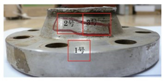
Figure 1 Macroscopic appearance and sampling locations of cracked flanges
1. Physical and chemical inspection
1.1 Macroscopic analysis
Macroscopic observation of the cracked part of the flange shows that the cracks were tortuously and intermittently distributed along the circumference of the flange neck, and there were no cracks at the flange plate. The outer surface of the flange neck had more cracks and larger gaps, as shown in Figure 2a; the inner surface of the flange neck had fewer and smaller cracks, as shown in Figure 2b. From this, it can be judged that the crack propagated from the outside to the inside.
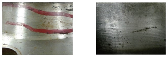
Figure 2 The morphology of the crack at the flange neck
1.2 The analysis of the chemical composition
Samples were taken at the No. 1 part shown in Figure 1, and the chemical composition of No. 1 sample was analyzed by a fixed full-spectrum direct-reading spectrometer. The results were shown in Table 1. It can be seen that the carbon content exceeds the standard technical requirements, and the titanium content is lower than the standard technical requirements; the contents of the other elements meet the requirements of NB/T 47010-2010 for S32168 stainless steel.
Table 1 The analysis results of chemical composition (mass fraction)
Figure 1 Macroscopic appearance and sampling locations of cracked flanges
1. Physical and chemical inspection
1.1 Macroscopic analysis
Macroscopic observation of the cracked part of the flange shows that the cracks were tortuously and intermittently distributed along the circumference of the flange neck, and there were no cracks at the flange plate. The outer surface of the flange neck had more cracks and larger gaps, as shown in Figure 2a; the inner surface of the flange neck had fewer and smaller cracks, as shown in Figure 2b. From this, it can be judged that the crack propagated from the outside to the inside.
Figure 2 The morphology of the crack at the flange neck
1.2 The analysis of the chemical composition
Samples were taken at the No. 1 part shown in Figure 1, and the chemical composition of No. 1 sample was analyzed by a fixed full-spectrum direct-reading spectrometer. The results were shown in Table 1. It can be seen that the carbon content exceeds the standard technical requirements, and the titanium content is lower than the standard technical requirements; the contents of the other elements meet the requirements of NB/T 47010-2010 for S32168 stainless steel.
Table 1 The analysis results of chemical composition (mass fraction)
| Items | C | Si | Mn | P | S | Cr | Ni | Ti |
| Measured values | 0.11 | 0.36 | 2.00 | 0.034 | 0.020 | 17.01 | 9.00 | 0.11 |
| Standard values | Less than and equal to 0.08 | Less than and equal to 1.00 | Less than and equal to 2.00 | Less than and equal to 0.035 | Less than and equal to 0.02 | 17.00 to 19.00 | 9.00 to 12.00 | 5wc to 0.70 |
| Please note that wc means carbon content. | ||||||||
1.3 Metallographic analysis
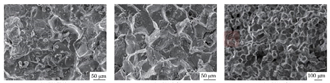
The metallographic sample was taken from the No. 2 part in Figure 1. After rough grinding, fine grinding, polishing and electrolytic etching with 10% (volume fraction) oxalic acid solution, it was observed under a metallographic microscope. The microstructure of the flange was single-phase austenite. According to GB/T6394-2002, the grain size grade was evaluated as 6.0 by the comparative method, as shown in Figure 3a. Precipitates and hard non-metallic inclusions were distributed in grain boundaries or grains under a magnification of 1000, as shown in Figure 3b.
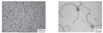
a) Low magnification b) High magnification
Figure 3 The microstructure and morphology of the flange
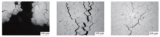
Observing the morphology of the crack of the metallographic sample, it can be seen that the crack's trunk and branches were obvious, and the crack developed along the grain; the tip was relatively sharp, which was a typical intergranular stress corrosion crack, as shown in Figure 4.
Observing the morphology of the crack of the metallographic sample, it can be seen that the crack's trunk and branches were obvious, and the crack developed along the grain; the tip was relatively sharp, which was a typical intergranular stress corrosion crack, as shown in Figure 4.
a) The top b) The middle c) The bottom
Figure 4 Microscopic morphology of cracks
1.4 SEM and EDS analysis
Using QUANTA200 scanning electron microscope (SEM) to observe the metallographic sample No. 2, it can be seen that there were a large number of precipitates at the grain boundaries, as shown in Figure 5. In Figure 1, the No. 3 part was sampled. Use a scanning electron microscope to observe the microscopic morphology of the crack section and energy dispersive spectroscopy (EDS) to analyze the composition of the corrosion products. Figure 6a shows the fracture morphology of the crack initiation zone on the outer surface of the flange neck. It can be seen that many corrosion products were attached to the fracture surface, forming a net-like cracked "mud pattern". Figure 6b shows the morphology of the central region of the crack, showing a crystal sugar like intergranular fracture, with a small number of corrosion products attached to the crystal surface, accompanied by secondary cracks. Figure 6c shows the morphology of the end of the crack, showing the characteristics of intergranular fracture. The secondary cracks and the polygonal smooth crystal surface were visible, and there are fewer corrosion products attached to the crystal surface. It can be seen that the crack expanded from the outside to the inside, which was consistent with the macroscopic analysis results.
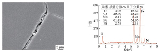
The composition of the hard non-metallic inclusions in the metallographic sample was analyzed by energy spectrum, as shown in Figure 7. Combined with its metallographic characteristics, it can be known that the inclusions were composite inclusions mainly composed of TiN. Figure 8 shows that the material at the grain boundary consists of chromium precipitates and corrosion products. Figure 9 shows the energy spectrum analysis results of the corrosion products on the crack surface, which are composed of corrosive elements such as chlorine, sulfur, and oxygen, as well as material matrix elements such as iron, chromium, manganese, and silicon.
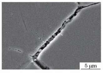
Figure 5 The SEM morphology of grain boundary precipitates
1.4 SEM and EDS analysis
Using QUANTA200 scanning electron microscope (SEM) to observe the metallographic sample No. 2, it can be seen that there were a large number of precipitates at the grain boundaries, as shown in Figure 5. In Figure 1, the No. 3 part was sampled. Use a scanning electron microscope to observe the microscopic morphology of the crack section and energy dispersive spectroscopy (EDS) to analyze the composition of the corrosion products. Figure 6a shows the fracture morphology of the crack initiation zone on the outer surface of the flange neck. It can be seen that many corrosion products were attached to the fracture surface, forming a net-like cracked "mud pattern". Figure 6b shows the morphology of the central region of the crack, showing a crystal sugar like intergranular fracture, with a small number of corrosion products attached to the crystal surface, accompanied by secondary cracks. Figure 6c shows the morphology of the end of the crack, showing the characteristics of intergranular fracture. The secondary cracks and the polygonal smooth crystal surface were visible, and there are fewer corrosion products attached to the crystal surface. It can be seen that the crack expanded from the outside to the inside, which was consistent with the macroscopic analysis results.
The composition of the hard non-metallic inclusions in the metallographic sample was analyzed by energy spectrum, as shown in Figure 7. Combined with its metallographic characteristics, it can be known that the inclusions were composite inclusions mainly composed of TiN. Figure 8 shows that the material at the grain boundary consists of chromium precipitates and corrosion products. Figure 9 shows the energy spectrum analysis results of the corrosion products on the crack surface, which are composed of corrosive elements such as chlorine, sulfur, and oxygen, as well as material matrix elements such as iron, chromium, manganese, and silicon.
Figure 5 The SEM morphology of grain boundary precipitates
a) The beginning area of the crack b) The middle part of the crack c) The tail of the crack
Figure 6 The SEM morphology of the fracture
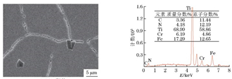
a) The SEM morphology b) The EDS spectrum
Figure 7 The SEM morphology and EDS spectrum of inclusions
a) The SEM morphology b) The EDS spectrum
Figure 8 The SEM morphology and EDS spectrum of grain boundary precipitates
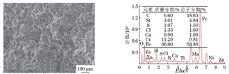
Figure 8 The SEM morphology and EDS spectrum of grain boundary precipitates
a) The SEM morphology b) The EDS spectrum
Figure 9 The SEM morphology and EDS spectrum of corrosion products on the crack surface
Figure 9 The SEM morphology and EDS spectrum of corrosion products on the crack surface

Related News
- Failure Analysis of Cracking in a 16MnⅢ Weld Neck Flange
- ANSYS Analysis for Anchor Flange Structural Optimization
- Flange Leakage in Hydrogen-Cooled Pipeline Systems of Thermal Power Plants
- Flange Sealing Technology and Installation Method for Hydrogenation Units
- Multi-Directional Die Forging Process for Horizontal Valve Bodies with Dual Flanges
- Structural Performance Analysis of Zirconium Pressure Vessel Lap Joint Flanges
- Low-Temperature Flange Sealing Solutions for Cryogenic Chemical Pipelines
- Innovative Technology for Automatic Alignment in Underwater Flange Assembly
- Stamped Steel Slip-On Flanges
- Design and Finite Element Analysis of Anchor Flanges for Oil & Gas Pipelines