Failures of Welding Seams of Slip-on Flanges of Thermal Pipelines
When the heating medium is hot water, the working pressure is up to 2.5MPa due to the low pressure of the thermal pipeline. When the heating medium is steam, the working pressure is up to 1.6MPa. Therefore, in the construction process, the pipeline and its components adopting low carbon steel can meet the requirements of use. In the construction process of a thermal company, the slip-on flange was broken. The welding process used electrode arc welding to fill and cover the surface. The material of the pipe and slip-on flange was Q235 steel, and the welding rod grade was E4303. In terms of raw material welding, the weldability of high carbon steel is the worst, followed by medium carbon steel; that of low carbon steel is better, and low carbon steel does not require preheating before welding, and heat treatment after welding. As an important component of the connection between the pipeline and the valve, the slip-on flange is directly related to the safe operation of the thermal pipeline, so the welding quality must be ensured in the welding process.
1. The analysis of the end
1.1 Macro detection
The fractured sample is shown in Figure 1. The fractured position is in the middle of the circular flange. The component has not been welded to the pipe, but is only at a fixed spot welding position. The flange fractures in the spot welding process. The fracture form is shown in Figure 2. The crack originates from the welding point and gradually extends to both ends. There is no deformation at the fracture site, and the fracture is even and straight, which belongs to brittle fracture.
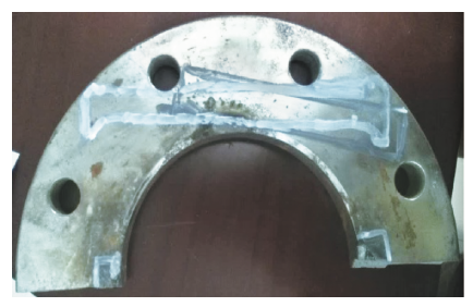
Figure 1 The samle for the fracture
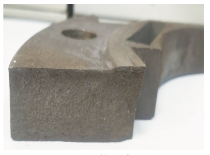
Figure 2 Fracture forms
1.2 Metallographic analysis
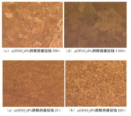
The fractured part was examined with an Axio Observer A1m microscope and the test results of different magnifications are shown in Figure 3. The test results in Figures 3a and b show that there is no crack between the grains of the structure, and no microscopic cracks were found for the magnification of 500 to 1000 times.
The test results in Figure 3 show that the microstructure is mainly composed of pearlite and cementite, and the cementite has good hardness but no plasticity. The strength and hardness of pearlite are moderate, and the toughness is good. Although the comprehensive performance of pearlite is better than that of cementite, the number of cementite in this structure is many and distributed in sheets. Therefore, the flange material has high strength, high hardness, and low toughness in the macroscopic aspect, and poor weldability in the welding aspect, which requires pre-welding preheating and post-welding heat treatment. After hardness testing, the surface hardness of the material is HB320.
1.3 The analysis of mechanical properties
After the fractured flange was sampled, the tensile and impact samples were processed, and the tensile and impact tests were carried out. The results of the tensile test and the fractured samples are shown in Figure 4.
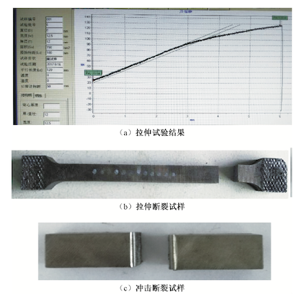
Figure 4
(a) Tensile test results (b) Samples for tensile fracture (c) Samples for impact fracture
It can be seen from Figure 4a that in the initial stage, the test curve rises linearly with a fixed slope, and an inflection point appears at the stretching distance of 3 mm. The slope of the curve becomes smaller, but does not become 0; it continues to rise with a fixed slope, and the tensile strength becomes 0 at 6 mm. The tensile test data shows that the tensile strength of the material is 856.02MPa. The sample has a yield point of 3 mm, no elastic stage, and directly breaks at 6 mm. The sample does not undergo elastic and plastic deformation, but directly produces brittle fracture; Figure 4b shows that the tensile fracture sample is brittle fracture. The fracture is neat. Figure 4c is the impact fracture sample, and the impact absorption energy is 34. 78J. From the above results, the material is characterized by high strength and low toughness.
1.4 Chemical composition analysis
The supply list shows that the material of the flange is Q235 low-carbon steel. The chemical composition of the steel sample was retested with the German SPECTRO TEST direct reading spectrometer. The test results are shown in Table 1, and the chemical composition of Q235 steel is shown in Table 2.
Table 1 Chemical composition of samples (%)
1. The analysis of the end
1.1 Macro detection
The fractured sample is shown in Figure 1. The fractured position is in the middle of the circular flange. The component has not been welded to the pipe, but is only at a fixed spot welding position. The flange fractures in the spot welding process. The fracture form is shown in Figure 2. The crack originates from the welding point and gradually extends to both ends. There is no deformation at the fracture site, and the fracture is even and straight, which belongs to brittle fracture.
Figure 1 The samle for the fracture
Figure 2 Fracture forms
1.2 Metallographic analysis
The fractured part was examined with an Axio Observer A1m microscope and the test results of different magnifications are shown in Figure 3. The test results in Figures 3a and b show that there is no crack between the grains of the structure, and no microscopic cracks were found for the magnification of 500 to 1000 times.
The test results in Figure 3 show that the microstructure is mainly composed of pearlite and cementite, and the cementite has good hardness but no plasticity. The strength and hardness of pearlite are moderate, and the toughness is good. Although the comprehensive performance of pearlite is better than that of cementite, the number of cementite in this structure is many and distributed in sheets. Therefore, the flange material has high strength, high hardness, and low toughness in the macroscopic aspect, and poor weldability in the welding aspect, which requires pre-welding preheating and post-welding heat treatment. After hardness testing, the surface hardness of the material is HB320.
1.3 The analysis of mechanical properties
After the fractured flange was sampled, the tensile and impact samples were processed, and the tensile and impact tests were carried out. The results of the tensile test and the fractured samples are shown in Figure 4.
Figure 4
(a) Tensile test results (b) Samples for tensile fracture (c) Samples for impact fracture
It can be seen from Figure 4a that in the initial stage, the test curve rises linearly with a fixed slope, and an inflection point appears at the stretching distance of 3 mm. The slope of the curve becomes smaller, but does not become 0; it continues to rise with a fixed slope, and the tensile strength becomes 0 at 6 mm. The tensile test data shows that the tensile strength of the material is 856.02MPa. The sample has a yield point of 3 mm, no elastic stage, and directly breaks at 6 mm. The sample does not undergo elastic and plastic deformation, but directly produces brittle fracture; Figure 4b shows that the tensile fracture sample is brittle fracture. The fracture is neat. Figure 4c is the impact fracture sample, and the impact absorption energy is 34. 78J. From the above results, the material is characterized by high strength and low toughness.
1.4 Chemical composition analysis
The supply list shows that the material of the flange is Q235 low-carbon steel. The chemical composition of the steel sample was retested with the German SPECTRO TEST direct reading spectrometer. The test results are shown in Table 1, and the chemical composition of Q235 steel is shown in Table 2.
Table 1 Chemical composition of samples (%)
| C | Si | Mn | P | S | Cr | Mo | Ni | Cu | V |
| 0.96 | 0.284 | 0.286 | 0.008 | 0.002 | 1.51 | 0.011 | 0.19 | 0.012 | 0.008 |
Table 2 Chemical composition of Q235 steel (%)
| C | Si | Mn | P | S |
| Less than and equal to 0. 22 | Less than and equal to 0. 35 | Less than and equal to 1. 4 | Less than and equal to 0. 045 | Less than and equal to 0. 050 |
It can be seen from the test results that there is a big gap between the chemical composition of the samples in Table 1 and the results in Table 2, especially C, Mn, Cr content. Therefore, it can be concluded that the flange material provided by the raw material supplier is not Q235 low carbon steel.

Related News
- Analysis of Loading-Port Flange Leakage in a Reactor Coolant Purification Resin Bed of a Power Plant
- Structural Design and Strength Analysis of a Deepwater Riser Suspension Flange
- Analysis of Heat Dissipation Losses in High-Temperature Flanges and Pipelines Used in Oil Refineries
- Failure and Crack Analysis of an EO/EG Unit Tower Inlet Flange
- Pipe Flange Bolt Tightening in LNG Projects: Key Considerations
- Ultrasonic Testing of High-Neck Flange Welds
- Underwater Flange Connection Methods for Submarine Pipelines
- Key Technologies for Pressure Vessel Testing and Flange Connection Design
- Installation of Main Bolts for Lap Joint Flange in High-Temperature Gas-Cooled Reactors
- Structural Design and Finite Element Analysis of Anchor Flanges