Application of TIG Welding to SS Slip-on Flanges (Part two)
4. Welding steps
(1) Requirements for base materials: stainless steel 304, 304L, 316, and 316L are used for slip-on flanges and pipe fittings, and it is better to use the same type of stainless steel for flanges and pipes. The diameter d of the inner hole of the slip-on flange is slightly larger than the outer diameter D of the pipe, and the ideal value is that d1 is equal to D2 plus 0.5 plus 0.1mm. Pipe wall thickness t is equal to 0.6 to 5.0mm, and the outer diameter of pipe D2 is equal to 6 to 500mm.
(2) Cleaning before welding: TIG welding is extremely sensitive to pollution, so the welding position of the weldment must be cleaned before welding. First, clean the burrs on the welded parts of the pipes and flanges to prevent oxide scales from being produced in the welding process. Second, clean the oil on the welding part. Generally, use acetone or alcohol to remove oil within 20 to 50mm on both sides of the welding part. Then the pipe passes through the inner hole of the flange from the non-sealing surface of the flange until it is 2 to 3mm away from the sealing surface of the flange.
(3) Welding at position 1 (Figure 1)
a. Perform self-fluxing welding without adding wire for the welding position 1.
b. Adjusting the welding current: The welding current of argon tungsten arc welding is usually selected according to the material, thickness of the workpiece and the spatial position of the joint. When the welding current increases, the penetration depth increases, and the width and reinforcement of the welding seam slightly increase. If the welding current is too great or too small, it will cause poor welding formation or welding defects. It is better to adjust the welding current to 80 to 110A at this position. The ideal current value is 90A. It is better to adjust the welding current to 150 to 180A for spot welding, and the ideal current value is 160A.
c. Adjusting the flow rate of argon gas: if the flow rate of argon gas is too small, the protective airflow will be weak, and the protection effect will not be good; defects such as gas holes and oxidation of the welding seam will easily occur; if the gas flow rate is too great, the turbulent flow will easily occur, and the protection effect will not be good. It will also affect the stable combustion of the arc. Welding at position 1 does not need to fill the parts with argon gas, only needs to adjust the gas flow of the welding torch, the argon gas flow is better adjusted to 7 to 101 per min.
d. Determining the welding speed: when the welding speed increases, the penetration depth and fusion width decrease. If the welding speed is too fast, it is easy to produce incomplete fusion and incomplete penetration. If the welding speed is too slow, the welding seam will be very wide, and leakages and perpetration may occur. When manual argon tungsten arc welding is performed, the welding speed is usually adjusted at any time according to the size and shape of the molten pool and the fusion of both sides.
e. Adjusting the extension length of the tungsten electrode: To prevent the arc from overheating and burning the nozzle, usually the tip of the tungsten electrode should extend beyond the nozzle. The distance from the tip of the tungsten electrode to the end face of the nozzle is the extended length of the tungsten electrode. The smaller the extension length of the tungsten electrode is, the closer the distance between the nozzle and the workpiece and the better the protection effect become. However, too small an extension length will hinder the observation of the molten pool. When welding the flange, the extension length of the tungsten electrode is preferably 3 to 6mm.
f. Spot welding at position 1 (Figure 2): place the weldment upwards on the rotating platform, and perform spot welding by hand. The degree of melting shall not affect the future complete welding seam. The diameter of the welding beam should not exceed the width of the welding seam after forming.
g: Continuous welding at welding position 1 (Figure 2): The distance between the tip of the tungsten electrode and the weldment is 2 to 3mm, and the horizontal distance from the edge is 2 to 5mm for welding. After pressing the start button on the welding torch, the welding machine starts to work. The air is supplied in advance and then the arc strike starts the formal welding. When the arc strike is started, the tungsten electrode should not directly contact the weldment to prevent the welding seam metal from drawing tungsten. The reliable method is to tilt the welding torch, and let the nozzle lean against the surface of the weldment first; make the electrode gradually approach the welding position to start the arc. Before the arc starts, the welding torch must be used to send air to the starting welding point 1.5 to 4s in advance to drive the air in the welding area. When the arc is done after welding, it is necessary to prevent arc craters and loss of protection. Generally, TIG welding machines are equipped with automatic current reduction. When the welding is stopped, the welding current decreases exponentially until the arc is extinguished, which can prevent arc crater cracks. When there is no current reduction device, the welding torch can be gradually raised, and then the power is cut off. At this time, the welding torch must still stay at the final welding position for 3 to 10 seconds. After the tungsten electrode and molten pool metal cool down, stop the gas supply and remove the welding torch to ensure the quality of the beginning and end of the welding seam.
h. Inspection of welding seams (Figure 3): The welding seam must be continuous, and the welding pattern should be fine and uniform. There should be no obvious protruding point at the start and end of the arc. If there are gas holes or needle holes in the welding seam, it should be welded again.
(4) Welding at position 2 (Figure 1)
a. When the wall thickness of the pipe fitting is less than and equal to 3mm, the weldment needs to be inflated for protection. Because the pipe wall is thin, the pipe will be penetrated in the welding process. If there is no gas protection, a black scale will appear in the welding seam of the pipe fittings, which will affect the welding quality. If the wall thickness of the pipe fittings is greater than 3mm, no gas protection is required.
b. Welding position 2 needs to be welded with wire, and a welding wire with a diameter of 2.0mm or 2.4mm is chosen.
c. Adjusting the welding current: It is better to adjust the welding current to 85 to 110A at this position; the ideal current value is 90A, and it is better to adjust the welding current to 150 to 180A in the spot welding process. The ideal current value is 160A.
d. Adjusting the flow rate of argon gas: adjust the flow rate of gas of the welding torch. It is better to adjust the argon gas’s flow rate to 7 to 101/min. If the wall thickness of the pipe fitting is less than or equal to 3mm, the back needs to be inflated for protection. When inflating the pipe fitting, an appropriate gas outlet should be left to prevent excessive gas pressure in the pipe during welding. At 25 to 50mm before the end of the root bead welding, it is necessary to ensure that the pressure of the gas in the pipe is not too high, to prevent the welding pool from blowing out or the root from being concave. It is better to enter from the bottom, let the air discharge upwards, and keep the gas outlet away from the welding seam, and adjust the flow of argon gas for inflation at the back to 6 to 151 per min.
e. Spot welding at position e (Figure 4): place the flange of the weldment downwards on the rotating platform, and perform spot welding at the welding part by hand. The degree of melting shall not affect the final complete welding. The diameter of the welding beam should exceed the width of the welding seam after forming.
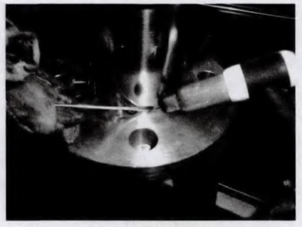
Figure 4 The position 2 before welding
f. Performing continuous welding at welding position 2 (Figure 4): the distance from the tip of the tungsten electrode to the weldment is 2 to 3mm, and the horizontal distance from the edge is 2 to 5mm for wire welding. The torch is tilted, so that the nozzle first leans against the surface of the weldment, and then the electrode gradually approaches the welding position to start the arc. The filler wire should be slowly sent to the front of the molten pool after forming a molten pool on the weldment, and should not be sent directly to the center of the molten pool. The welding wire cannot leave the argon protection zone. Otherwise, it will be oxidized by the air; the welding wire cannot touch the tungsten electrode. The argon flow must also not be disturbed. Before starting the arc, use the welding torch to send air to the starting welding point 1.5 to 4 seconds in advance to drive the air into the welding area. Stop the gas supply and remove the welding torch to prevent arc craters and premature loss of protection to ensure the quality of the beginning and end of the welding seam.
g: Welding seam inspection (Figure 5): The welding seam must be continuous; the welding lines should be fine and uniform, and there should be no obvious protruding points at the starting and closing arcs. If there are gas holes or needle holes in the welding seam, it should be re-welded.
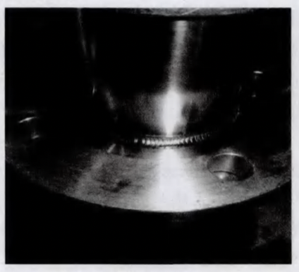
Figure 5 The position 2 after welding
(5) After welding, remove the scale and dirt on the surface of the stainless steel, so that the welding seam can obtain a clean and bright surface, which is conducive to the formation of a passivation film to improve its corrosion resistance.
5. Evaluation of the protection effect
It can be evaluated by the color of the welding area, as shown in Table 1.
Table 1
(1) Requirements for base materials: stainless steel 304, 304L, 316, and 316L are used for slip-on flanges and pipe fittings, and it is better to use the same type of stainless steel for flanges and pipes. The diameter d of the inner hole of the slip-on flange is slightly larger than the outer diameter D of the pipe, and the ideal value is that d1 is equal to D2 plus 0.5 plus 0.1mm. Pipe wall thickness t is equal to 0.6 to 5.0mm, and the outer diameter of pipe D2 is equal to 6 to 500mm.
(2) Cleaning before welding: TIG welding is extremely sensitive to pollution, so the welding position of the weldment must be cleaned before welding. First, clean the burrs on the welded parts of the pipes and flanges to prevent oxide scales from being produced in the welding process. Second, clean the oil on the welding part. Generally, use acetone or alcohol to remove oil within 20 to 50mm on both sides of the welding part. Then the pipe passes through the inner hole of the flange from the non-sealing surface of the flange until it is 2 to 3mm away from the sealing surface of the flange.
(3) Welding at position 1 (Figure 1)
a. Perform self-fluxing welding without adding wire for the welding position 1.
b. Adjusting the welding current: The welding current of argon tungsten arc welding is usually selected according to the material, thickness of the workpiece and the spatial position of the joint. When the welding current increases, the penetration depth increases, and the width and reinforcement of the welding seam slightly increase. If the welding current is too great or too small, it will cause poor welding formation or welding defects. It is better to adjust the welding current to 80 to 110A at this position. The ideal current value is 90A. It is better to adjust the welding current to 150 to 180A for spot welding, and the ideal current value is 160A.
c. Adjusting the flow rate of argon gas: if the flow rate of argon gas is too small, the protective airflow will be weak, and the protection effect will not be good; defects such as gas holes and oxidation of the welding seam will easily occur; if the gas flow rate is too great, the turbulent flow will easily occur, and the protection effect will not be good. It will also affect the stable combustion of the arc. Welding at position 1 does not need to fill the parts with argon gas, only needs to adjust the gas flow of the welding torch, the argon gas flow is better adjusted to 7 to 101 per min.
d. Determining the welding speed: when the welding speed increases, the penetration depth and fusion width decrease. If the welding speed is too fast, it is easy to produce incomplete fusion and incomplete penetration. If the welding speed is too slow, the welding seam will be very wide, and leakages and perpetration may occur. When manual argon tungsten arc welding is performed, the welding speed is usually adjusted at any time according to the size and shape of the molten pool and the fusion of both sides.
e. Adjusting the extension length of the tungsten electrode: To prevent the arc from overheating and burning the nozzle, usually the tip of the tungsten electrode should extend beyond the nozzle. The distance from the tip of the tungsten electrode to the end face of the nozzle is the extended length of the tungsten electrode. The smaller the extension length of the tungsten electrode is, the closer the distance between the nozzle and the workpiece and the better the protection effect become. However, too small an extension length will hinder the observation of the molten pool. When welding the flange, the extension length of the tungsten electrode is preferably 3 to 6mm.
f. Spot welding at position 1 (Figure 2): place the weldment upwards on the rotating platform, and perform spot welding by hand. The degree of melting shall not affect the future complete welding seam. The diameter of the welding beam should not exceed the width of the welding seam after forming.
g: Continuous welding at welding position 1 (Figure 2): The distance between the tip of the tungsten electrode and the weldment is 2 to 3mm, and the horizontal distance from the edge is 2 to 5mm for welding. After pressing the start button on the welding torch, the welding machine starts to work. The air is supplied in advance and then the arc strike starts the formal welding. When the arc strike is started, the tungsten electrode should not directly contact the weldment to prevent the welding seam metal from drawing tungsten. The reliable method is to tilt the welding torch, and let the nozzle lean against the surface of the weldment first; make the electrode gradually approach the welding position to start the arc. Before the arc starts, the welding torch must be used to send air to the starting welding point 1.5 to 4s in advance to drive the air in the welding area. When the arc is done after welding, it is necessary to prevent arc craters and loss of protection. Generally, TIG welding machines are equipped with automatic current reduction. When the welding is stopped, the welding current decreases exponentially until the arc is extinguished, which can prevent arc crater cracks. When there is no current reduction device, the welding torch can be gradually raised, and then the power is cut off. At this time, the welding torch must still stay at the final welding position for 3 to 10 seconds. After the tungsten electrode and molten pool metal cool down, stop the gas supply and remove the welding torch to ensure the quality of the beginning and end of the welding seam.
h. Inspection of welding seams (Figure 3): The welding seam must be continuous, and the welding pattern should be fine and uniform. There should be no obvious protruding point at the start and end of the arc. If there are gas holes or needle holes in the welding seam, it should be welded again.
(4) Welding at position 2 (Figure 1)
a. When the wall thickness of the pipe fitting is less than and equal to 3mm, the weldment needs to be inflated for protection. Because the pipe wall is thin, the pipe will be penetrated in the welding process. If there is no gas protection, a black scale will appear in the welding seam of the pipe fittings, which will affect the welding quality. If the wall thickness of the pipe fittings is greater than 3mm, no gas protection is required.
b. Welding position 2 needs to be welded with wire, and a welding wire with a diameter of 2.0mm or 2.4mm is chosen.
c. Adjusting the welding current: It is better to adjust the welding current to 85 to 110A at this position; the ideal current value is 90A, and it is better to adjust the welding current to 150 to 180A in the spot welding process. The ideal current value is 160A.
d. Adjusting the flow rate of argon gas: adjust the flow rate of gas of the welding torch. It is better to adjust the argon gas’s flow rate to 7 to 101/min. If the wall thickness of the pipe fitting is less than or equal to 3mm, the back needs to be inflated for protection. When inflating the pipe fitting, an appropriate gas outlet should be left to prevent excessive gas pressure in the pipe during welding. At 25 to 50mm before the end of the root bead welding, it is necessary to ensure that the pressure of the gas in the pipe is not too high, to prevent the welding pool from blowing out or the root from being concave. It is better to enter from the bottom, let the air discharge upwards, and keep the gas outlet away from the welding seam, and adjust the flow of argon gas for inflation at the back to 6 to 151 per min.
e. Spot welding at position e (Figure 4): place the flange of the weldment downwards on the rotating platform, and perform spot welding at the welding part by hand. The degree of melting shall not affect the final complete welding. The diameter of the welding beam should exceed the width of the welding seam after forming.
Figure 4 The position 2 before welding
f. Performing continuous welding at welding position 2 (Figure 4): the distance from the tip of the tungsten electrode to the weldment is 2 to 3mm, and the horizontal distance from the edge is 2 to 5mm for wire welding. The torch is tilted, so that the nozzle first leans against the surface of the weldment, and then the electrode gradually approaches the welding position to start the arc. The filler wire should be slowly sent to the front of the molten pool after forming a molten pool on the weldment, and should not be sent directly to the center of the molten pool. The welding wire cannot leave the argon protection zone. Otherwise, it will be oxidized by the air; the welding wire cannot touch the tungsten electrode. The argon flow must also not be disturbed. Before starting the arc, use the welding torch to send air to the starting welding point 1.5 to 4 seconds in advance to drive the air into the welding area. Stop the gas supply and remove the welding torch to prevent arc craters and premature loss of protection to ensure the quality of the beginning and end of the welding seam.
g: Welding seam inspection (Figure 5): The welding seam must be continuous; the welding lines should be fine and uniform, and there should be no obvious protruding points at the starting and closing arcs. If there are gas holes or needle holes in the welding seam, it should be re-welded.
Figure 5 The position 2 after welding
(5) After welding, remove the scale and dirt on the surface of the stainless steel, so that the welding seam can obtain a clean and bright surface, which is conducive to the formation of a passivation film to improve its corrosion resistance.
5. Evaluation of the protection effect
It can be evaluated by the color of the welding area, as shown in Table 1.
Table 1
| Colors of the welding areas | Protective effects |
| Silver, gold and yellow | The best |
| Blue | Good |
| Gray | Bad |
| Black | Extremely bad |
6. Conclusion
The TIG welding technology implements self-fluxing welding of the flange sealing surface, and wire welding of the non-sealing surface of the flange can well meet the requirements for welding of the flange and the pipe fittings, ensuring that the inside and outside of the welding seam are uniform and beautiful; the color of the welding seam is silvery white. It meets the requirements of flanges.

Related News
- Analysis of Loading-Port Flange Leakage in a Reactor Coolant Purification Resin Bed of a Power Plant
- Structural Design and Strength Analysis of a Deepwater Riser Suspension Flange
- Analysis of Heat Dissipation Losses in High-Temperature Flanges and Pipelines Used in Oil Refineries
- Failure and Crack Analysis of an EO/EG Unit Tower Inlet Flange
- Pipe Flange Bolt Tightening in LNG Projects: Key Considerations
- Ultrasonic Testing of High-Neck Flange Welds
- Underwater Flange Connection Methods for Submarine Pipelines
- Key Technologies for Pressure Vessel Testing and Flange Connection Design
- Installation of Main Bolts for Lap Joint Flange in High-Temperature Gas-Cooled Reactors
- Structural Design and Finite Element Analysis of Anchor Flanges