Inspection of Stainless Steel Flanges of LNG Gasification Stations
Abstract: After an LNG gasification station was put into operation for 10 years, leakage due to corrosion was found in the heat-affected zone of the stainless steel flange at the liquid phase inlet of the air-temperature gasifier and the gas phase outlet of the storage tank from the supercharger. Chemical composition analysis, metallographic microstructure analysis of the heat-affected zone and corrosion failure mechanism analysis were carried out on the stainless steel flange base metal.
1. Overview
In petrochemical equipment, austenitic stainless steel is widely used due to its excellent mechanical properties, corrosion resistance and ultra-low temperature toughness. An LNG gasification station was put into operation in September 2007. From February 7, 2017, the operator on duty successively inspected the inside of the stainless steel flange welding joint of the liquid phase inlet of the air-heated gasifier and the gas phase outlet of the storage tank self-supercharger and leakage occurs. There are 20 stainless steel flanges at the inlet and outlet of the supercharger for air-heated vaporizers and storage tanks in this station. On-site detection for leakage was carried out on the inner side of the stainless steel flange welding seams, and 5 parts leaked, with a leakage rate of 25%. Through on-site leak detection, it is found that the leaks were distributed in a circular shape along the inner side of the welding junction, and the leaks were located in the heat-affected zone of the welded joint.
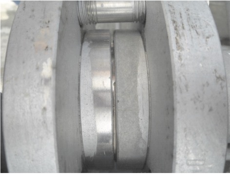
Through on-site investigation and review of relevant equipment information and on-site measurement of flange dimensions, it was found that the inlet and outlet flanges of the air-heated gasifier and self-supercharger in this station were non-standard tongue and groove flanges. In addition, the sealing surface of the flange connected with the air-temperature vaporizer and the self-supercharger body is made from aluminum alloy, and the matching flange sealing surface is made from stainless steel (Figure 1). The left sealing surface of the lap joint flange is made from stainless steel, and the right aluminum alloy. Because the lap joint flange with tongue and groove surface is supplied by the manufacturer, and the manufacturer has gone bankrupt, its manufacturing process cannot be traced.

Figure 1 On-site assembly of the lap joint flange
In order to find out the cause of cracking caused by corrosion in the heat affected zone of the flange, and avoid the recurrence of similar leakage caused by corrosion in the heat affected zone of the stainless steel flange welded junction. The chemical composition of the failed flange, the metallographic microstructure of the heat-affected zone and the corrosion failure mechanism are analyzed. The conclusion of the failure of the stainless steel lap joint flange was come to, and corresponding measures were taken, which provide a reference for the construction and operation of the LNG gasification station in the future.
2. Experimental methods
The chemical composition of the base material of the stainless steel lap joint flange and the base material of the stainless steel pipe is detected by X-ray fluorescence spectroscopy to determine whether the material meets the requirements. The crack area and the unwelded base metal area were sampled, mechanically polished and ground, and observed with a stereo microscope to observe the macroscopic morphology of the crack. After grinding, polishing, and etching, the microstructure is analyzed to observe the metallographic structure and determine the type of corrosion.
3. Experimental results
3.1 Macroscopic morphology
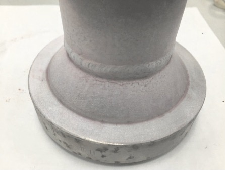
Surface penetration testing was carried out on the welding joints with leaks, and it was found that there were cracks in the welding heat-affected zone, which were strip-shaped and distributed circularly along the inside of the welding seam, as shown in Figure 2.

Figure 2
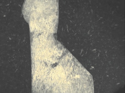
Figure 2 Stereo microscope observation of the section of the welded joint shows that the cracks were distributed radially, and the cracks start from the outer wall of the flange sealing surface and extend to the inner wall, as shown in Figure 3.

Figure 3 Macroscopic morphology of cracks in the leakage area
3.2 Chemical composition
The chemical composition of the base material of the sealing surface of the stainless steel lap joint flange and the base material of the stainless steel pipe was detected by X-ray fluorescence spectroscopy, and compared with that of the standard austenitic stainless steel 304. The results are shown in Table 1. In Table 1, w represents the quality fraction. The mass fraction of each component of the standard austenitic stainless steel 304 is specified in GB/T14976-2012 "Stainless Steel Seamless Steel Tubes for Fluid Transmission".
Table 1 Chemical composition of metals
1. Overview
In petrochemical equipment, austenitic stainless steel is widely used due to its excellent mechanical properties, corrosion resistance and ultra-low temperature toughness. An LNG gasification station was put into operation in September 2007. From February 7, 2017, the operator on duty successively inspected the inside of the stainless steel flange welding joint of the liquid phase inlet of the air-heated gasifier and the gas phase outlet of the storage tank self-supercharger and leakage occurs. There are 20 stainless steel flanges at the inlet and outlet of the supercharger for air-heated vaporizers and storage tanks in this station. On-site detection for leakage was carried out on the inner side of the stainless steel flange welding seams, and 5 parts leaked, with a leakage rate of 25%. Through on-site leak detection, it is found that the leaks were distributed in a circular shape along the inner side of the welding junction, and the leaks were located in the heat-affected zone of the welded joint.
Through on-site investigation and review of relevant equipment information and on-site measurement of flange dimensions, it was found that the inlet and outlet flanges of the air-heated gasifier and self-supercharger in this station were non-standard tongue and groove flanges. In addition, the sealing surface of the flange connected with the air-temperature vaporizer and the self-supercharger body is made from aluminum alloy, and the matching flange sealing surface is made from stainless steel (Figure 1). The left sealing surface of the lap joint flange is made from stainless steel, and the right aluminum alloy. Because the lap joint flange with tongue and groove surface is supplied by the manufacturer, and the manufacturer has gone bankrupt, its manufacturing process cannot be traced.

Figure 1 On-site assembly of the lap joint flange
In order to find out the cause of cracking caused by corrosion in the heat affected zone of the flange, and avoid the recurrence of similar leakage caused by corrosion in the heat affected zone of the stainless steel flange welded junction. The chemical composition of the failed flange, the metallographic microstructure of the heat-affected zone and the corrosion failure mechanism are analyzed. The conclusion of the failure of the stainless steel lap joint flange was come to, and corresponding measures were taken, which provide a reference for the construction and operation of the LNG gasification station in the future.
2. Experimental methods
The chemical composition of the base material of the stainless steel lap joint flange and the base material of the stainless steel pipe is detected by X-ray fluorescence spectroscopy to determine whether the material meets the requirements. The crack area and the unwelded base metal area were sampled, mechanically polished and ground, and observed with a stereo microscope to observe the macroscopic morphology of the crack. After grinding, polishing, and etching, the microstructure is analyzed to observe the metallographic structure and determine the type of corrosion.
3. Experimental results
3.1 Macroscopic morphology
Surface penetration testing was carried out on the welding joints with leaks, and it was found that there were cracks in the welding heat-affected zone, which were strip-shaped and distributed circularly along the inside of the welding seam, as shown in Figure 2.

Figure 2
Figure 2 Stereo microscope observation of the section of the welded joint shows that the cracks were distributed radially, and the cracks start from the outer wall of the flange sealing surface and extend to the inner wall, as shown in Figure 3.

Figure 3 Macroscopic morphology of cracks in the leakage area
3.2 Chemical composition
The chemical composition of the base material of the sealing surface of the stainless steel lap joint flange and the base material of the stainless steel pipe was detected by X-ray fluorescence spectroscopy, and compared with that of the standard austenitic stainless steel 304. The results are shown in Table 1. In Table 1, w represents the quality fraction. The mass fraction of each component of the standard austenitic stainless steel 304 is specified in GB/T14976-2012 "Stainless Steel Seamless Steel Tubes for Fluid Transmission".
Table 1 Chemical composition of metals
| wC /% | Standard austenitic stainless steel 304 | Base materials of flange sealing surfaces | Base materials of stainless steel tubes |
| wSi /% | less than and equal to 0.08 | 0.180 | 0.074 |
| wMn /% | less than and equal to 1.00 | 0.385 | 0.524 |
| wP /% | less than and equal to 2.00 | 2.399 | 1.083 |
| wS /% | less than and equal to 0.035 | 0.0287 | 0.0323 |
| wCr /% | less than and equal to 0.030 | 0.0047 | 0.0019 |
| wNi /% | 18.00 to 20.00 | 16.284 | 17.112 |
| wC /% | 8.00 to 11.00 | 6.347 | 8.198 |
Figure 2 Stereo microscope observation of the section of the welded joint shows that the cracks were radially distributed, and the cracks started from the outer wall of the flange sealing surface and extended to the inner wall, as shown in Figure 3.
It can be seen from Table 1 that the chemical composition of the base metal of the stainless steel lap joint flange sealing surface is not within the standard range, and the material of the flange sealing surface does not meet the standard requirements. Among them, the C content seriously exceeds the standard, and the Mn content also exceeds the standard requirement. At the same time, the contents of Cr and Ni are lower than the standard requirements.
3.3 Metallographic structure
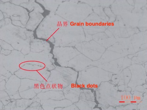
The optical microscope was used to observe the crack position and its vicinity in the heat-affected zone of the welded joint of the stainless steel lap joint flange sealing surface. Figure 4 is the observed metallographic diagram. It can be seen from the metallographic diagram that the corrosion of the heat-affected zone is cracking caused by corrosion along the grain boundary. In addition, it can be seen from the metallographic diagram in Figure 4 that there were black dots on the grain boundaries near the heat-affected zone, which are Cr23C6 carbides produced in the welding process.

Figure 4 Metallographic diagram of the crack position and its vicinity in the heat-affected zone of the welded joint
Related News
- Structural Design and Strength Analysis of a Deepwater Riser Suspension Flange
- Analysis of Heat Dissipation Losses in High-Temperature Flanges and Pipelines Used in Oil Refineries
- Failure and Crack Analysis of an EO/EG Unit Tower Inlet Flange
- Pipe Flange Bolt Tightening in LNG Projects: Key Considerations
- Ultrasonic Testing of High-Neck Flange Welds
- Underwater Flange Connection Methods for Submarine Pipelines
- Key Technologies for Pressure Vessel Testing and Flange Connection Design
- Installation of Main Bolts for Lap Joint Flange in High-Temperature Gas-Cooled Reactors
- Structural Design and Finite Element Analysis of Anchor Flanges
- Key Welding Technology for High-Neck Flange and Steel Pipe Joints

