Structure of Austenitic SS Bellows & F6NM Martensitic SS Flanges after Welding (Part One)
Abstract
The microstructure and mechanical properties of the welded joints of 316Ti stainless steel bellows used for valves and F6NM martensitic stainless steel flanges in the as-welded state and post-weld heat treatment (PWHT) were studied in this article. The results showed that the welding seam was well formed in the as-welded state and post-weld heat treatment, and there were no cracks and other obvious defects. After the heat treatment, the size of the weld metal and the crystal grains in the HAZ zone were the same, and the distribution was more uniform than the as-welded state; in the as-welded state, the average hardness of the weld metal was about HVo.1170, which was slightly higher than the hardness of the weld metal in the PWHT state. The average hardness of the heat-affected zone of the post-weld heat treatment is about HV0.1 360, which was higher than the hardness of the as-welded state. The post-weld heat treatment can significantly reduce the residual stress of the bellows expansion joint, but does not affect its internal structure and hardness.
The stainless steel bellows is a metal elastic sealing element widely used in modern industry. The strength formed by its closed shapes and wall thicknesses bears the pressure of the medium, and the elastic characteristics are realized by the bending of the corrugated side. In the field of valves, bellows dynamic sealing is the key technology to ensure zero leakages of valves, and it is the most effective and reliable dynamic sealing technology. The metal bellows dynamic seal in the valve is realized by the metal bellows assembly. The metal bellows assembly is generally welded by the metal bellows and the flange.
316Ti stainless steel has good plastic toughness, hot and cold processing characteristics. It has good corrosion resistance in PWR nuclear power plants, can resist acid corrosion, and has low radiation sensitivity. It is also widely used in fast reactors and thermal power fields. 316Ti is usually selected as the material for the manufacture of loop valve bellows in nuclear power plants based on the above characteristics.
The research on valve bellows is now mostly concentrated on analysis and research of the design, manufacture and stress for bellows, but there are very few researches on the welding of bellows and flanges. The valve bellows assembly is the key part to finally realize the dynamic sealing and elastic performance of the valve. The welding quality of the bellows and flange is a crucial factor. Therefore, it is necessary to research on the organization and performance of the welding of the valve bellows and flange. In this study, the 316Ti stainless steel bellows (7 layers) used in nuclear valves were welded with F6NM martensitic stainless steel flanges to study the microstructure and mechanical properties of the welded joints in as-welded state and post-weld heat treatment (PWHT), as well as the influence of as-welded state and post-weld heat treatment on the mechanical properties and residual stress of the bellows.
1. Test materials and methods
1.1 Test materials
The bellows used in the test is made from 316Ti stainless steel, and the welded joint's size is φ49 mm x 7 mm x 0.3 mm. It was formed by cold pressing after being superimposed by 7 layers of thin-walled cylinders with a thickness of 0.3 mm, a length of 90 mm, a total of 11 rolls. The test flange is made from F6NM martensitic stainless steel, and the welding joint's size is φ49.5 mm x 2.8 mm. The selected welding wire is ERNiCr-3 with φ1.0 mm. The chemical composition of base metal and welding material is shown in Table 1.
Table 1 The chemical composition of base metal and welding wire (mass fraction) (%)
| C | Si | Mn | P | S | Cr | Ni | Mo | Cu | Ti | ||
| Base metal | 316Ti | 0.023 | 0.583 | 0.939 | 0.029 | 0.001 | 16.840 | 10.58 | 2.007 | 2.007 | 0.373 |
| F6NM | 0.028 | 0.34 | 0.79 | 0.02 | 0.0007 | 12.72 | 4.34 | 0.52 | 0.12 | 0.001 | |
| Welding wire | ERNiCr-3 | 0.01 | <0.1 | 3.2 | 0.002 | 0.001 | 20.5 | 72.5 | _ | 0.2 | _ |
The joint type of the bellows and flange was an end joint. The joint form is shown in Figure 1. Manual TIG welding was used. The welding process is protected by argon gas. Each bellows was welded with one flange at both ends. Prepared two samples of the bellows assembly with the same parameters. One bellows assembly was at the as-welded state, and the other bellows assembly was subjected to post heat treatment at 560℃ for 8 hours. The two bellows samples were all qualified after testing by the NDE test, and the helium leak test was carried out under the test pressure of 10 to 3MPa; the leakage rate was less than 10 to 4 Pa.L/s, and the sealing effect was good.
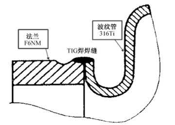
Figure 1 Schematic diagram of welded joints
1.2 Test methods
Marked the two samples respectively, and used the X-ray diffraction to measure the residual stress of the bellows' seventh expansion joint before and after cutting the as-welded and PWHT bellows assembly. Cross-cutting was performed on the seventh expansion joint of the bellows, and then cut longitudinally at angles of 0° and 180°. Used optical microscopes and micro-nano indentation hardness testers to observe and measure microstructure and microhardness of the cross section of each layer of bellows in the root, middle and top of the U-shaped ring at angles of 0° and 180° of the seventh expansion joint. Cut the 9th ring of the bellows transversely, and took the upper part welded to the flange. Cut longitudinally in the 60°, 180° and 300° directions of the sample. Observed and measured the microstructure and microhardness of the welded area at every angle with an optical microscope and a micro-nano indentation hardness tester. Marking and sampling are shown in Figure 2.
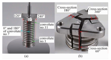
Figure 2 Marking and taking samples
2. Results and discussion
2.1 The analysis of the microstructure of the welding area
Welded joints can be divided into 7 areas: 316Ti bellows base metal (defined as A1 zones), 316Ti bellows side heat affected zones HAZ (defined as C1 zones), F6NM flange base metal (defined as A2 zones), F6NM flange side heat affected zones HAZ (Defined as B2 zones), F6NM flange side fusion zones (defined as C2 zones), and weld metal (defined as D zones). Used an optical microscope to observe the interface of the welding seam of the as-welded and PWHT welded joints, as shown in Figure 3. It can be seen from Figure 3 that in the as-welded state and PWHT state, the welded seam of the bellows and flange showed a good shape without cracks and other obvious defects.
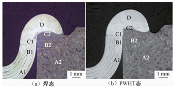
(a) The as-welded state (b) The PWHT state
Figure 3 The welding seam's interface of the welded joint in the as-welded and PWHT state
Observed the heat-affected zone, fusion zone and weld metal zone on the side of the 316Ti bellows, as shown in Figure 4.
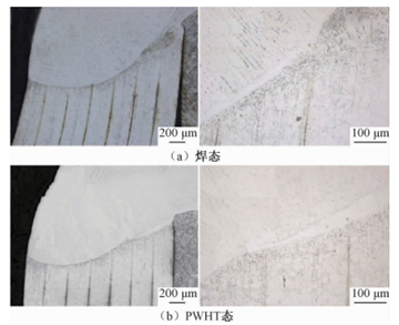
Figure 4 Microstructure of HAZ, fusion zone and weld metal zone on the side of 316Ti bellows
It can be seen from Figure 4a that the base metal of 316Ti bellows and weld metal in the as-welded state were well combined, and there were a few black needles in the weld metal area. This was mainly due to the martensitization of the weld metal during the welding process and the partial austenite martensitization in the fusion zone, but the grain refinement in the heat-affected zone, fusion zone and weld metal zone was uniform. The grains gradually increased from the fusion zone to the heat-affected zone, and the distribution was uniform. The black needles in the weld metal area and the fusion zone of 316Ti bellows in the PWHT state have disappeared, and the original martensite was transformed into austenite, as shown in Figure 4b. The grain size was the same, and the distribution of grains in each zone was more uniform than the welded state.
Figure 3 The welding seam's interface of the welded joint in the as-welded and PWHT state
Observed the heat-affected zone, fusion zone and weld metal zone on the side of the 316Ti bellows, as shown in Figure 4.
Figure 4 Microstructure of HAZ, fusion zone and weld metal zone on the side of 316Ti bellows
It can be seen from Figure 4a that the base metal of 316Ti bellows and weld metal in the as-welded state were well combined, and there were a few black needles in the weld metal area. This was mainly due to the martensitization of the weld metal during the welding process and the partial austenite martensitization in the fusion zone, but the grain refinement in the heat-affected zone, fusion zone and weld metal zone was uniform. The grains gradually increased from the fusion zone to the heat-affected zone, and the distribution was uniform. The black needles in the weld metal area and the fusion zone of 316Ti bellows in the PWHT state have disappeared, and the original martensite was transformed into austenite, as shown in Figure 4b. The grain size was the same, and the distribution of grains in each zone was more uniform than the welded state.

Related News
- Analysis of Loading-Port Flange Leakage in a Reactor Coolant Purification Resin Bed of a Power Plant
- Structural Design and Strength Analysis of a Deepwater Riser Suspension Flange
- Analysis of Heat Dissipation Losses in High-Temperature Flanges and Pipelines Used in Oil Refineries
- Failure and Crack Analysis of an EO/EG Unit Tower Inlet Flange
- Pipe Flange Bolt Tightening in LNG Projects: Key Considerations
- Ultrasonic Testing of High-Neck Flange Welds
- Underwater Flange Connection Methods for Submarine Pipelines
- Key Technologies for Pressure Vessel Testing and Flange Connection Design
- Installation of Main Bolts for Lap Joint Flange in High-Temperature Gas-Cooled Reactors
- Structural Design and Finite Element Analysis of Anchor Flanges